
Apparatus for use in reclaiming coolant used in cutting machines

a technology for reclaiming equipment and cutting machines, which is applied in the direction of gravity filters, filter loosening material filters, maintenance and safety accessories, etc. it can solve the problems of inability to dispose of coolant and lubricant after, problems with prior art recovery devices and systems, and generally expensive installation, maintenance and operation. , to achieve the effect of low manufacturing cost, convenient use and not requiring a lot of linear spa

Inactive Publication Date: 2005-12-20
MIOC ALEX
View PDF9 Cites 4 Cited by
  • Summary
  • Abstract
  • Description
  • Claims
  • Application Information

AI Technical Summary

Benefits of technology

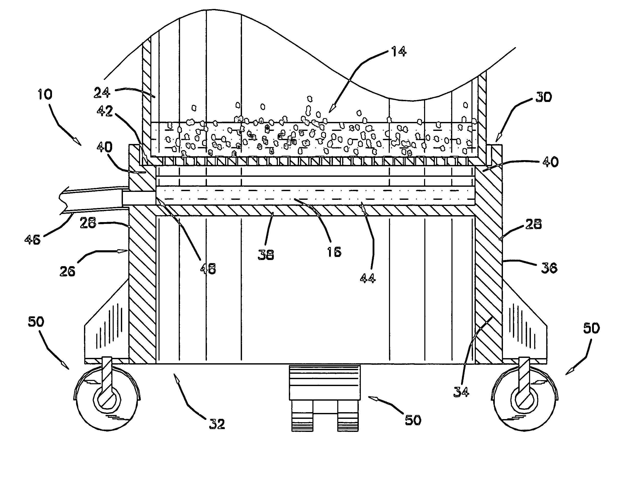
"The present invention provides an apparatus for reclaiming coolant used in cutting machines. The apparatus includes a wheeled cart with a shallow receptacle for supporting a barrel that cuttings are deposited into during a milling operation of a work piece. The collected coolant is returned by gravity via a drain line. The apparatus has several technical effects, including reclaiming a greater amount of coolant from cuttings, reducing coolant loss resulting in decreased pollution and costs, not requiring motive means to return collected coolant back to the coolant system of a cutting machine, being easily moved from location to location, continuously redirecting reclaimed coolant to the coolant system of the cutting machine, having a low cost of manufacture with regard to both materials and labor, and being economically available to the buying public."

Problems solved by technology

With the expense of the coolants and the lubricants and their ecological effects on the environment it is not practical to dispose the coolant and lubricant after a single use.
However, the prior art recovery devices and systems have been problematic and generally expensive to install, maintain and operate.

Method used


Image

  • Apparatus for use in reclaiming coolant used in cutting machines
  • Apparatus for use in reclaiming coolant used in cutting machines
  • Apparatus for use in reclaiming coolant used in cutting machines

Examples


Embodiment Construction

[0028]Referring now to the drawings, and particularly to FIGS. 1–3, a preferred embodiment of the apparatus for reclaiming coolant used in cutting machines of the present invention is shown and generally designated by the reference numeral 10.

[0029]In FIG. 1, a new and improved apparatus for use in reclaiming coolant used in cutting machines 10 of the present invention for reclaiming used coolant is illustrated and will be described. The apparatus 10 is illustrated in use schematically with a typical machine tool 12 for milling or otherwise cutting or removing discrete cuttings 14 from a work piece. During a machine operation, it is conventional to deliver a supply of liquid coolant 16 to a part of the machine tool or to the work piece being machined. The used or discharged coolant 16 accumulates in a collection reservoir 18, which is typically positioned below the machine tool 12. The cuttings 14 intermixed with the coolant 12 are intercepted from collecting in the reservoir 18 by ...


PUM

PropertyMeasurementUnit
inner diameteraaaaaaaaaa
outer diameteraaaaaaaaaa
diameteraaaaaaaaaa

Abstract

An apparatus for reclaiming coolant used in cutting machines and for returning the reclaimed coolant to the coolant system of the cutting machine is provided. The apparatus includes a shallow receptacle for supporting a barrel that cuttings are deposited into during a milling operation of a work piece. The apparatus includes a flange that extends from an inner surface of the receptacle and supports the bottom of the barrel allowing coolant to drain from the barrel into the receptacle. The collected coolant is returned to the coolant system of the cutting machine by gravity via a drain line. The apparatus further includes a plurality of casters allowing the apparatus along with the supported barrel to be moved from location to location relatively easy.

Description

BACKGROUND OF THE INVENTION[0001]1. Field of the Invention[0002]The present invention relates generally to coolant recovery systems for machine tools. More particularly, relating to an apparatus for more effectively reclaiming used coolant and returning the reclaimed coolant to a coolant supply tank for reuse.[0003]2. Background of the Prior Art[0004]It is known to use liquid coolants and lubricants during machining operations. The coolants and lubricants increase the performance of the machine tool and prevent over heating of the machine tool and the work piece. The coolants and lubricants also serve the purpose of flushing away cuttings from the machine tool and the work piece during the machining operation. With the expense of the coolants and the lubricants and their ecological effects on the environment it is not practical to dispose the coolant and lubricant after a single use. Accordingly, many prior art devices have been developed to recover used coolants and lubricants from...

Claims


Application Information

Patent Timeline
Patent Type & Authority Patents(United States)
IPC IPC(8): B23Q11/00
CPCB23Q11/0057Y02P70/10
Inventor MIOC, ALEX
Owner MIOC ALEX
Learn More