Eureka AIR delivers breakthrough ideas for toughest innovation challenges, trusted by R&D personnel around the world.

Multimode transmission system using TDMA

a transmission system and multi-mode technology, applied in transmission, high-level techniques, energy consumption reduction, etc., can solve problems such as interference from main data transmission, inability to accurately inability to properly fulfill scientific and communications missions, so as to improve satellite transmission performance, reduce the number of antennas and modulators required, and improve the effect of reliability

Inactive Publication Date: 2005-12-13
HUGHES ELECTRONICS
View PDF10 Cites 72 Cited by
  • Summary
  • Abstract
  • Description
  • Claims
  • Application Information

AI Technical Summary

Benefits of technology

[0007]It is, therefore, an object of the invention to provide an improved and reliable multimode transmission system using TDMA. Another object of the invention is to reduce the number of antennas and modulators required in a satellite. An additional object of the invention is to improve satellite transmission performance.
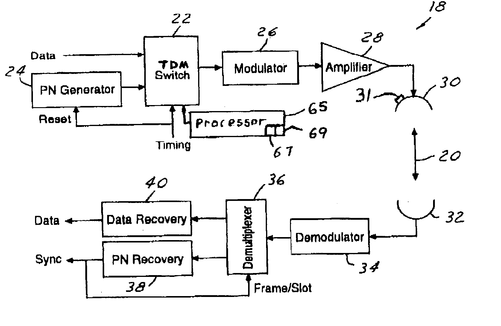
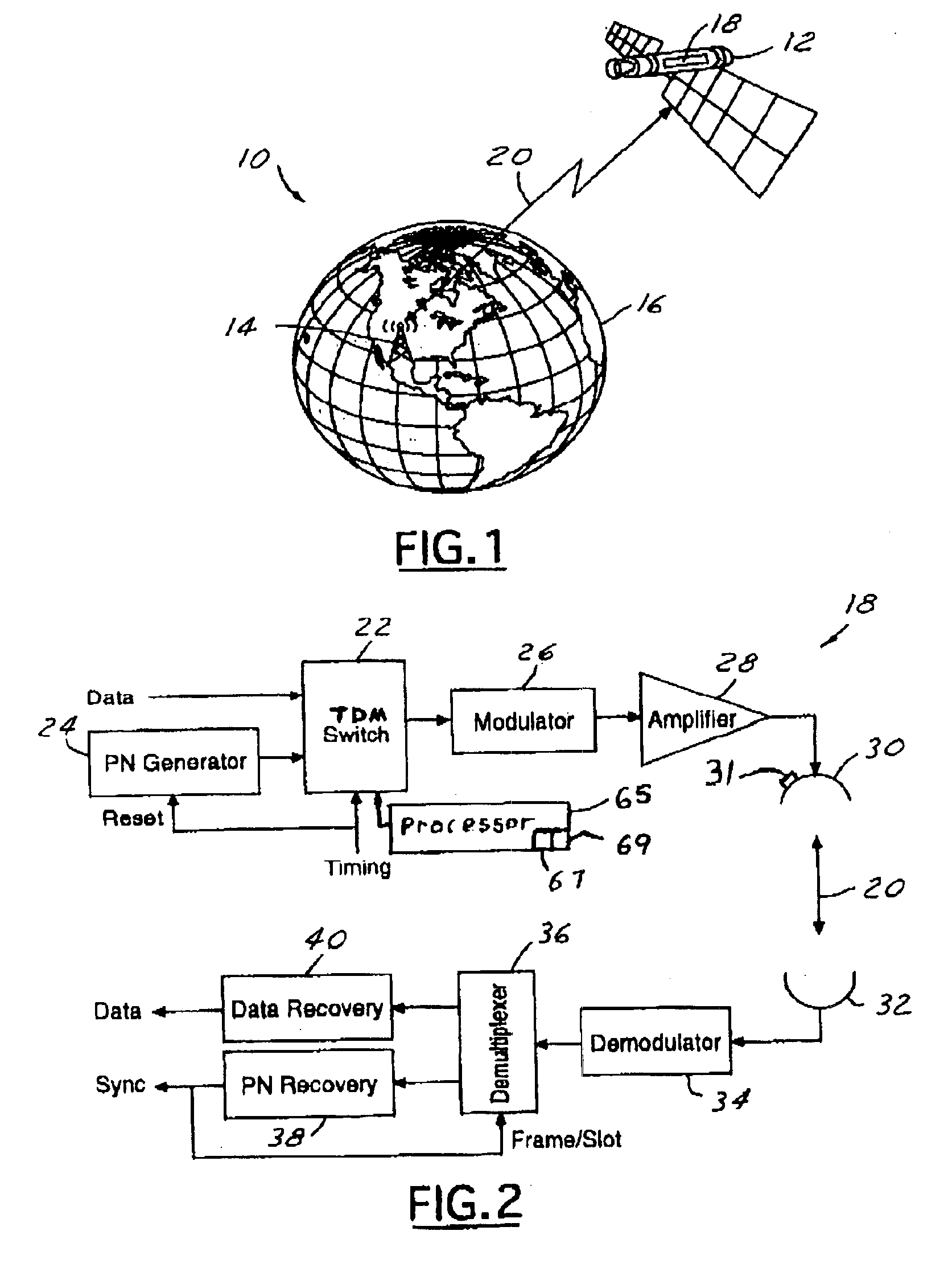
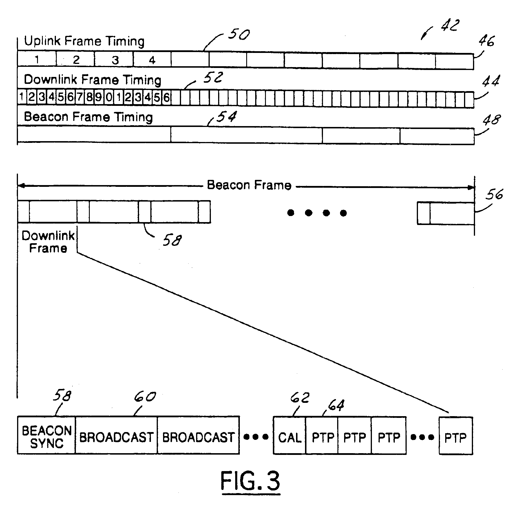
[0008]In accordance with the objects of this invention, a multimode transmission system using TDMA is provided. In one embodiment of the invention, A multimode transmission system using TDMA provides a plurality of satellite services to a ground station terminal. These services include timing beacon synchronization, multi-cast / broadcast data service, calibration data, and point-to-point data service. The multimode transmission system uses a TDM switch to generate a TDMA signal having a plurality of TDMA transmission frames. Each TDMA transmission frame includes a plurality of downlink frame time slots. Each time slot may be of variable length and is dynamically allocated to an individual satellite service based upon demand. The TDMA signal is then broadcast using an advanced transmit antenna system, which requires beam-shaping and beam power control features, to enable TDMA switching between shaped beams and spot beam modes of the antenna. These antenna features allow for the dynamic partitioning of satellite system capacity between wide-area broadcasts and localized point-to-point service and efficient utilization of the satellite transmission power.
[0009]The present invention thus achieves an improved multimode transmission system using TDMA. The present invention is advantageous in that it reduces the number of antennas and demodulators required in the terminal and allows a single terminal, with a single antenna, to receive all types of satellite service.

Problems solved by technology

These scientific and communications missions, however, cannot be accurately fulfilled without uploading and downloading electronic data.
Without the capability to receive and transmit electronic data, proper satellite function is hindered and at times impossible.
Unfortunately, typical satellites require multiple antennas and the associated electronics (modulators with frequency division multiplexing plans) required for each antenna for each of the above functions.
In addition to the added complexity in the generation and recovery of the beacon signal, the conventional approach has a number of inherent problems.
First, there is a concern with possible interference from the main data transmission.
Second, a small bandwidth can limit the timing accuracy of the beacon.
The disadvantages associated with these conventional satellite transmission techniques have made it apparent that a new technique for satellite multimode transmission using time division multiple access is needed.

Method used


Image

  • Multimode transmission system using TDMA
  • Multimode transmission system using TDMA
  • Multimode transmission system using TDMA

Examples


Embodiment Construction

[0015]In the following figures, the same reference numerals will be used to identify identical components in the various views. The present invention is illustrated with respect to a multimode transmission system using TDMA, particularly suited for the aerospace field. However, the present invention is applicable to various other uses that may require multimode transmission system using TDMA.

[0016]Referring to FIG. 1, a perspective view of a satellite system 10 in accordance with one embodiment of the present invention is illustrated. The satellite system 10 is comprised of one or more satellites 12 in communication with a ground station 14 located on the Earth 16. Each satellite 12 contains one or more multimode transmission systems 18 using TDMA for allowing a terminal located in ground station 14 to receive multiple satellite services.

[0017]In a satellite system 10 employing TDMA for multiple access for uplink and downlink transmission 20, data is sent in bursts on the allocated ...


PUM


Abstract

A multimode transmission system using TDMA provides a plurality of satellite services to a ground station terminal. These services include timing beacon synchronization, multi-cast / broadcast data service, calibration data, and point-to-point data service. The multimode transmission system uses a TDM switch to generate a TDMA signal having a plurality of TDMA transmission frames. Each TDMA transmission frame includes a plurality of downlink frame time slots. Each time slot may be of variable length and is dynamically allocated to an individual satellite service based upon demand. The TDMA signal is then broadcast using an advanced transmit antenna system, which requires beam-shaping and beam power control features, to enable TDMA switching between shaped beams and spot beam modes of the antenna. These antenna features allow for the dynamic partitioning of satellite system capacity between wide-area broadcasts and localized point-to-point service and efficient utilization of the satellite transmission power.

Description

TECHNICAL FIELD[0001]The present invention relates generally to satellite communication systems, and more particularly to a multimode transmission system using time division multiple access (TDMA).BACKGROUND ART[0002]Satellites and other spacecraft are in widespread use for various purposes including scientific research and communications. These scientific and communications missions, however, cannot be accurately fulfilled without uploading and downloading electronic data. In many applications, the satellite relies upon uploading and downloading electronic data for position correction or system diagnostics. In other applications, the satellite acts as a relay to transfer data between two remote points on the Earth. Without the capability to receive and transmit electronic data, proper satellite function is hindered and at times impossible.[0003]Many modern spacecraft act as relays to transfer data between two or more points on the Earth. There are several types of electronic data t...

Claims


Application Information

Patent Timeline
IPC IPC(8): H04B7/212H04L12/50
CPCH04B7/212Y02D30/70
Inventor VAUGHAN, ROBERT E.ROSEN, HAROLD
Owner HUGHES ELECTRONICS
Why Eureka
Eureka Blog
Learn More