
Magnetic random access memory using memory cells with rotated magnetic storage elements

a magnetic storage element and random access technology, applied in the field of memory circuits, can solve problems such as unfavorable reduction of array efficiency, and achieve the effect of optimizing read and write operations and reducing the size of memory cells

Inactive Publication Date: 2005-12-13
GLOBALFOUNDRIES US INC
View PDF4 Cites 2 Cited by
  • Summary
  • Abstract
  • Description
  • Claims
  • Application Information

AI Technical Summary

Benefits of technology

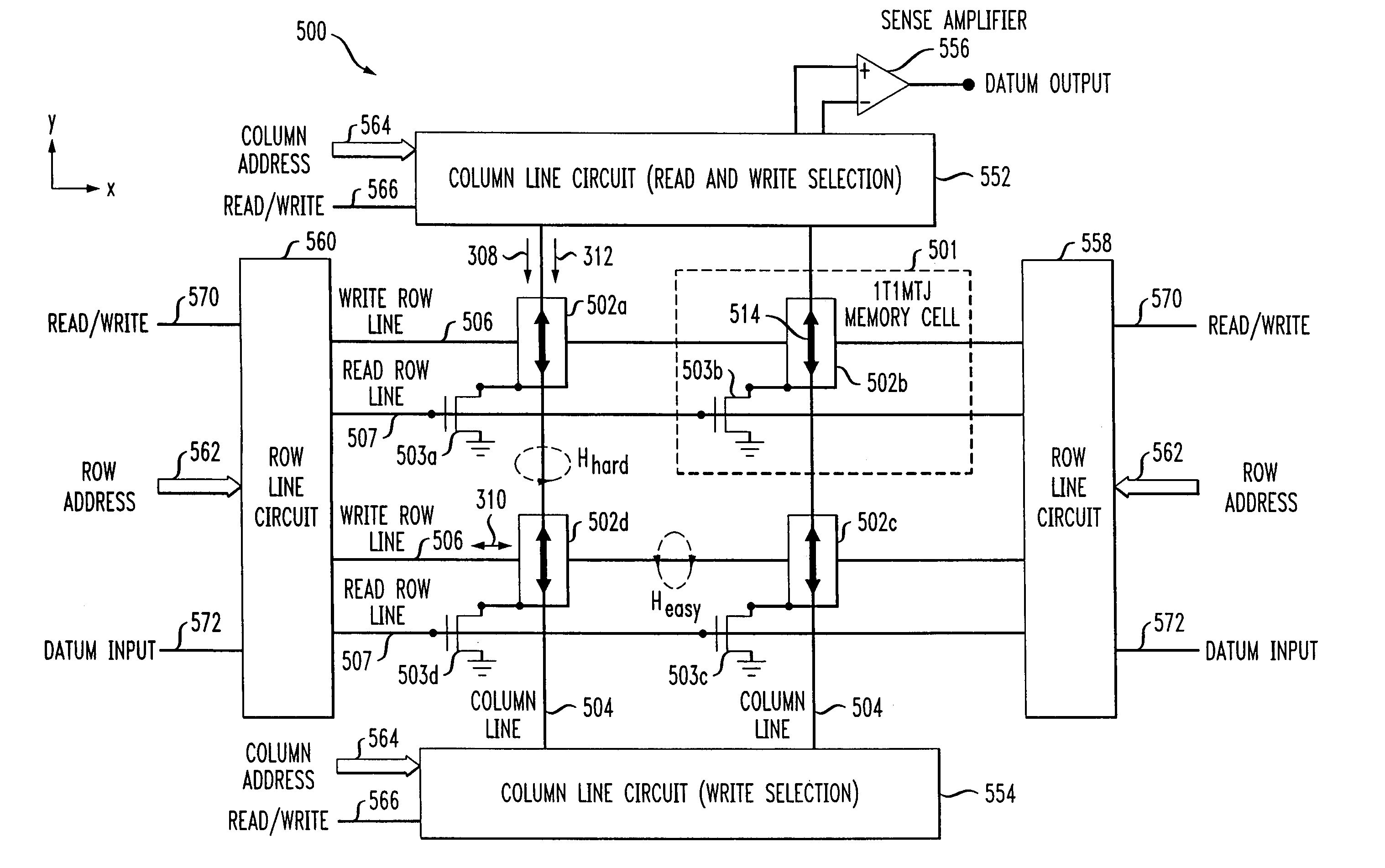
The present invention provides techniques for forming an MRAM circuit with multiple memory cells arranged in a way that optimizes read and write operations. By selectively rotating magnetic storage elements, the easy and hard axes of each cell are aligned with the direction of current flow, allowing for separate read and write lines for each cell. This results in a more efficient and compact memory circuit. Additionally, the invention can reduce the size of memory cells within a lTlMTJ MRAM circuit.

Problems solved by technology

Therefore, reducing the number of memory cells along a bit line dimension to increase read access time, as previously stated, without also increasing the number of memory cells along a word line dimension would undesirably reduce the array efficiency, which can be defined as a percentage of the total semiconductor area devoted to the memory cells.

Method used


Image

  • Magnetic random access memory using memory cells with rotated magnetic storage elements
  • Magnetic random access memory using memory cells with rotated magnetic storage elements
  • Magnetic random access memory using memory cells with rotated magnetic storage elements

Examples


Embodiment Construction

[0023]The present invention will be described herein in the context of an illustrative cross-point MRAM array. The invention, however, is more generally applicable to techniques for improving the read access time of an MRAM array by providing an architecture in which read and write ports associated with at least a portion of the memory cells in the array are spatially separated from one another. Although implementations of the present invention may be described herein with reference to magnetic tunnel junction (MTJ) devices, it should be appreciated that the invention is not limited to such devices, and that other suitable devices, such as, for example, other magneto-resistive memory elements, may be similarly employed with or without modifications to the inventive magnetic memory architecture.

[0024]As will be understood by those skilled in the art, “word lines” are generally defined as being oriented in a row or horizontal direction and are used during a conventional write operatio...


PUM


Abstract

A magnetic random access memory circuit comprises a plurality of magnetic memory cells, each of the memory cells including a magnetic storage element having an easy axis and a hard axis associated therewith, and a plurality of column lines and row lines for selectively accessing one or more of the memory cells, each of the memory cells being proximate to an intersection of one of the column lines and one of the row lines. Each of the magnetic memory cells is arranged such that the easy axis is substantially parallel to a direction of flow of a sense current and the hard axis is substantially parallel to a direction of flow of a write current.

Description

CROSS-REFERENCE TO RELATED APPLICATION[0001]This application is a divisional of U.S. application Ser. No. 10 / 446,297, filed on May 28, 2003, now U.S. Pat. No. 6,816,431 the disclosure of which is incorporated by reference herein.STATEMENT OF GOVERNMENT RIGHTS[0002]This invention was made with Government support under grant contract number MDA972-99-C-0009 awarded by the Defense Advanced Research Projects Agency (DARPA) of the United States Department of Defense. The Government has certain rights in this invention.FIELD OF THE INVENTION[0003]The present invention relates generally to memory circuits, and more particularly relates to a magnetic random access memory (MRAM) circuit employing rotated magnetic storage elements.BACKGROUND OF THE INVENTION[0004]FIG. 1A illustrates a conventional magnetic tunnel junction (MTJ) device 100. The MTJ 100 is typically comprised of a stack of two ferromagnetic layers (ML) separated by a tunnel barrier (TL) at a cross-point of two conductors, one o...

Claims


Application Information

Patent Timeline
Patent Type & Authority Patents(United States)
IPC IPC(8): G11C7/00G11C11/15G11C11/16
CPCG11C11/16
Inventor LU, YUREOHR, WILLIAM ROBERTSCHEUERLEIN, ROY EDWIN
Owner GLOBALFOUNDRIES US INC
Learn More