Method of fabricating a damage tolerant shaft

a technology of damage tolerance and shaft, which is applied in the field of shafts, can solve the problems of accidental damage that the drive shaft must withstand damage to the composite materials, and the potential damage to the drive shaft, so as to achieve the effect of increasing the radius, wall thickness and/or weight of the drive shaft, and adding the strength of the sha

Inactive Publication Date: 2005-12-13
THE BOEING CO
View PDF11 Cites 3 Cited by
  • Summary
  • Abstract
  • Description
  • Claims
  • Application Information

AI Technical Summary

Benefits of technology

[0011]The damage tolerant shaft and method of fabricating a damage tolerant shaft of the present invention provide a drive shaft that is tolerant of accidental and projectile damage to a portion of the drive shaft. Thus, the damage tolerant drive shaft is able to continue to properly operate after being partially damaged because the design of the shaft permits it to continue carrying the required torque loads and the corresponding internal shear stresses. The damage tolerant shaft and associated method are particularly advantageous because the shaft provides damage tolerance without increasing the radius, wall thickness and / or weight of the drive shaft.
[0013]Another advantageous embodiment of a damage tolerant shaft includes a plurality of lobes and a filler material disposed between portions of adjacent lobes. The lobes are shaped relative to one another such that they may be positioned to define an annular body and a plurality of ribs extending within the annular body. The lobes may be formed of a composite material and each lobe may contain reinforcing fibers extending at least partially about a respective lobe. Additional reinforcing fibers oriented in a direction perpendicular to the axis about which the annular body is symmetrical may extend through the ribs to increase the strength of the shaft. An outer layer, which also may be formed of composite material, may surround the lobes to further define the annular body. The composite material of the outer layer may also contain reinforcing fibers extending at least partially about the lobes. If an outer layer surrounds the lobes, a filler material may also be disposed within interstices between the outer layer and the plurality of lobes.
[0017]The lobes of the ribs of the damage tolerant shaft may be reinforced with a plurality of reinforcing fibers oriented in a direction perpendicular to an axis about which the annular body is symmetrical. The additional reinforcing fibers that extend through the thickness of the lobes of the damage tolerant shaft provide additional strength for the shaft, particularly for the portion of the shaft that remains after the shaft is partially damaged. Furthermore, although the damage tolerant shaft has internal ribs that a conventional drive shaft does not, the additional strength provided by the internals ribs allows for a thinner annular body of the damage tolerant shaft than the outer wall of the conventional drive shaft, such that the weight of the damage tolerant shaft is equal to or less than the weight of a conventional drive shaft.
[0018]Thus, the damage tolerant shaft and associated method of fabricating a damage tolerant shaft provide a drive shaft that is tolerant of accidental and projectile damage to a portion of the drive shaft. As such, the damage tolerant shaft is able to continue to carry the required torque loads and the corresponding internal shear stresses after the damage. In addition, the shaft and associated method of fabrication achieve damage tolerance without increasing the radius, wall thickness and / or weight of the drive shaft.

Problems solved by technology

In addition, the design process must take into account the potential for damage to the drive shaft.
Many of the vehicles that utilize drive shafts are weight-sensitive, such as automobiles and aircraft that have weight limits under which they can safely and / or efficiently operate.
One type of damage that drive shafts made of composite materials must withstand is damage to the composite materials.
The damage may occur accidentally during handling, such as dropping or hitting the drive shaft.
While the individual layers of fibers have a very high strength, the adherence between the layers is not as strong and may be damaged by an impact such that the fiber layers or plies separate, which is commonly called delamination.
The damaged portion of the drive shaft locally becomes an open cross-section, which decreases the torque load that the drive shaft can carry because the internal shear stresses in that portion of the drive shaft no longer flow about a closed path.
This type of damage can be difficult to determine by visual inspection.
Without repair, however, the damage will weaken the drive shaft and affect its ability to carry a torque load.
Another type of damage that the drive shaft must withstand is damage from projectiles.
For example, the drive shafts of military rotorcraft may experience damage from ballistic projectiles; and the drive shafts of automobiles may experience damage from rocks and other debris that may hit an exposed drive shaft.
Experience has shown that ballistic projectiles that hit along the edge of a shaft and create a “slit” along the edge of the shaft can significantly reduce the torsional strength of a shaft, while projectiles that hit in the center of a shaft and create separate entry and exit “holes” only moderately reduce the strength of the shaft.
The damage to the drive shaft may occur when the vehicle is in operation such that the drive shaft must remain operable in order to safely land and / or bring the vehicle to a stop and repair the damage.
Safely landing and / or bringing the vehicle to a stop is difficult, however, because, like the damage due to accidents during handling, the projectile damage also creates a locally open section of the shaft, which decreases the torque load that the drive shaft can carry.
This approach suffers from the drawback that the weight of the drive shaft correspondingly increases, which is what the designers try to avoid.
The increase in damage tolerance of this approach, however, is fairly limited, particularly regarding projectile damage.
This approach is often not available to the designer of a drive shaft because of space limitations.

Method used


Image

  • Method of fabricating a damage tolerant shaft
  • Method of fabricating a damage tolerant shaft
  • Method of fabricating a damage tolerant shaft

Examples


Embodiment Construction

[0026]The present invention now will be described more fully hereinafter with reference to the accompanying drawings, in which preferred embodiments of the invention are shown. This invention may, however, be embodied in many different forms and should not be construed as limited to the embodiments set forth herein; rather, these embodiments are provided so that this disclosure will be thorough and complete, and will fully convey the scope of the invention to those skilled in the art. Like numbers refer to like elements throughout.

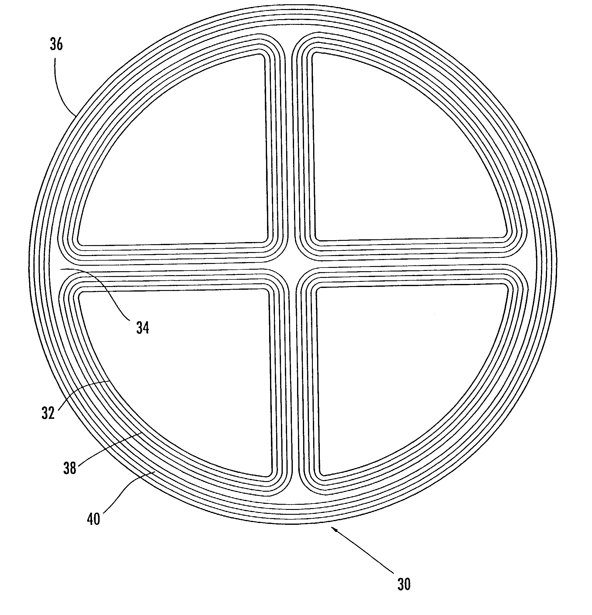
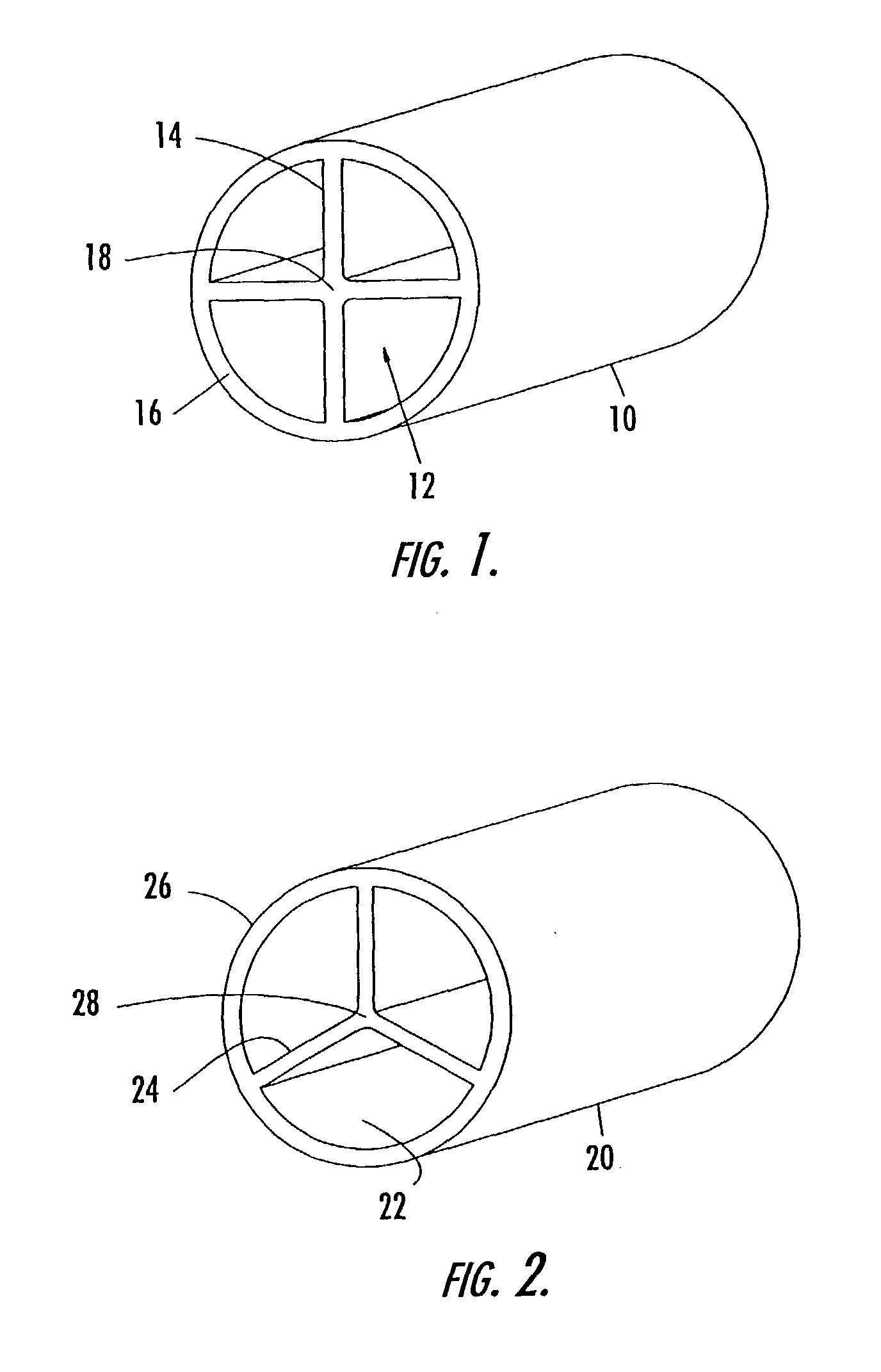
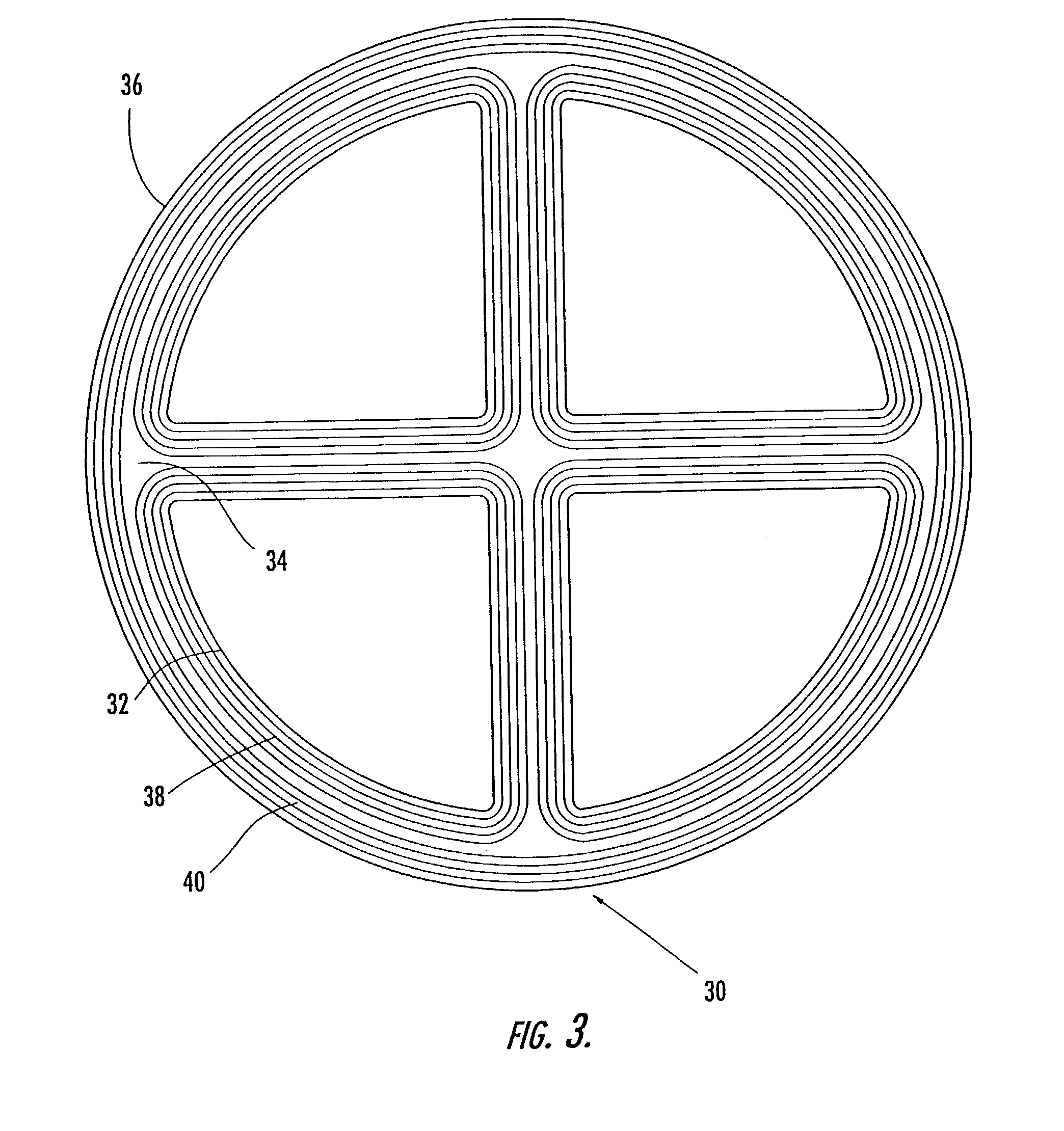
[0027]The damage tolerant shaft 10 according to one embodiment of the present invention is depicted in FIG. 1. As shown, the shaft includes an annular body 16 that is symmetrical about an axis and ribs 14 that extend inwardly from the annular body 16. The axis generally extends lengthwise through the annular body 16 at a location coincident with the center of the annular body 16. The ribs 14 also extend lengthwise along the annular body 16 and connect with...


PUM

PropertyMeasurementUnit
anglesaaaaaaaaaa
anglesaaaaaaaaaa
torqueaaaaaaaaaa

Abstract

A method of fabricating a damage tolerant shaft is provided in which a plurality of lobes are initially formed and are then positioned relative to one another to define an annular body and a plurality of ribs extending within the annular body. The plurality of lobes are formed of a plurality of reinforcing fibers extending at least partially about a respective lobe. Once the lobes have been positioned relative to one another, interstices between portions of adjacent lobes may be filled. Additionally, the plurality of lobes may be surrounded by an outer layer, also formed of reinforcing fibers extending at least partially about the plurality of lobes. The plurality of lobes may be impregnated with resin and cured, either prior to being positioned relative to one another or thereafter.

Description

CROSS-REFERENCE TO RELATED APPLICATIONS[0001]This application is a divisional of U.S. application Ser. No. 10 / 058,952, filed Jan. 28, 2002, the contents of which are incorporated herein in their entirety by reference.FIELD OF THE INVENTION[0002]This invention relates to a shaft with internal connecting ribs that is tolerant of damage to a portion of the shaft because a closed path formed by the undamaged segment of the shaft and the internal connecting ribs continue to carry the torque loading on the shaft.BACKGROUND OF THE INVENTION[0003]Drive shafts are used in various vehicles, such as automobiles, aircrafts and rotorcrafts. Drive shafts generally connect a rotatable member to an engine that drives the rotation. The engine power rotates the drive shaft, which, in turn, rotates the workpiece. For example, rotorcrafts, such as helicopters, have drive shafts between the rotor, gearboxes and the fuselage-mounted engine(s) to enable the engine to drive the rotation of the rotor blades...

Claims


Application Information

Patent Timeline
Patent Type & Authority Patents(United States)
IPC IPC(8): F16C3/02
CPCF16C3/026A63B59/0014B29L2031/603B29C70/48B29C70/462B29L2031/75A63B60/08A63B60/06A63B60/10
Inventor HOLEMANS, PETERMINGUET, PIERRE
Owner THE BOEING CO
Why Eureka
Try Eureka