
Valve device for faucet or spray gun

a valve device and spray gun technology, applied in the field of valve devices, can solve the problems of water leakage problem, water leaking problem, and typical valve devices or control devices may not be used to selectively flow upwards through shower nozzles, spray guns, shower nozzles,

Active Publication Date: 2005-12-13
YANG TSAI CHEN
View PDF6 Cites 17 Cited by
  • Summary
  • Abstract
  • Description
  • Claims
  • Application Information

AI Technical Summary

Benefits of technology

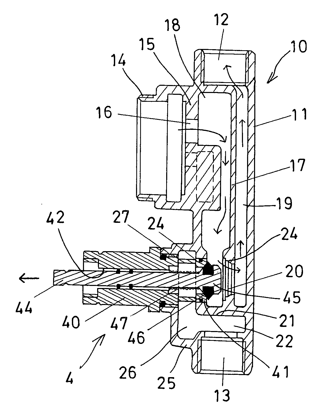
"The present invention is a valve device that allows water to be supplied upwardly to shower nozzles or downwardly to spray guns. The valve device includes a receptacle with an upper and lower port for connecting to different spray devices. The receptacle has a vertical partition with a lower aperture and a front wall with an upper orifice. The receptacle also has a lateral panel attached to the vertical partition to separate the front chamber and the rear chamber. The front chamber is connected to the housing via the orifice of the front wall, while the rear chamber is connected to the upper port of the receptacle. The receptacle also has a lower casing attached to the front wall with a chamber formed therein and connected to the lower port of the receptacle via a space between the lateral panel and the lower port of the receptacle. The casing also has a passage formed therein and a stem slidably received in the passage. The stem has a plug selectively engageable with the ring member of the tubular member and the valve seat of the vertical partition to control the water flow. The invention provides an improved valve device for supplying water to different spray devices."

Problems solved by technology

However, the typical valve devices or control devices may not be used to control the water to selectively flow upwardly through shower nozzles, or downwardly through spray guns, shower nozzles, or other sprayer devices.
In the valve receptacles of the typical valve devices or control devices, a water leaking problem may occur due to wrongly designed valve receptacles.

Method used


Image

  • Valve device for faucet or spray gun
  • Valve device for faucet or spray gun
  • Valve device for faucet or spray gun

Examples


Embodiment Construction

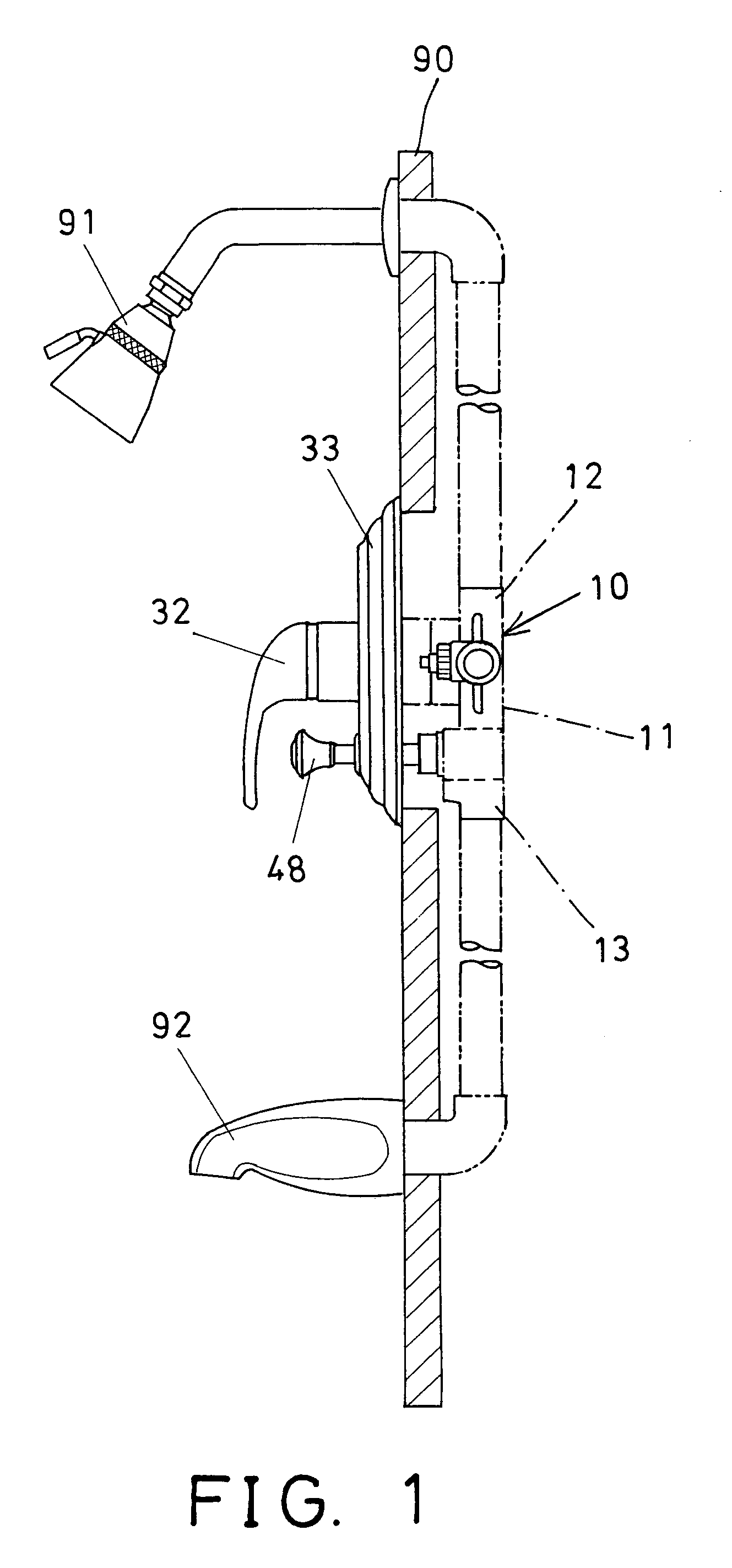
[0019]Referring to the drawings, and initially to FIG. 1, a valve device 10 in accordance with the present invention comprises a valve receptacle 11 to be built into wall members 90 (FIG. 1) and including an upper port 12 and a lower port 13 for coupling to upward shower nozzles 91 and to downward spray guns 92, shower nozzles 93 (FIG. 7), or other sprayer devices.

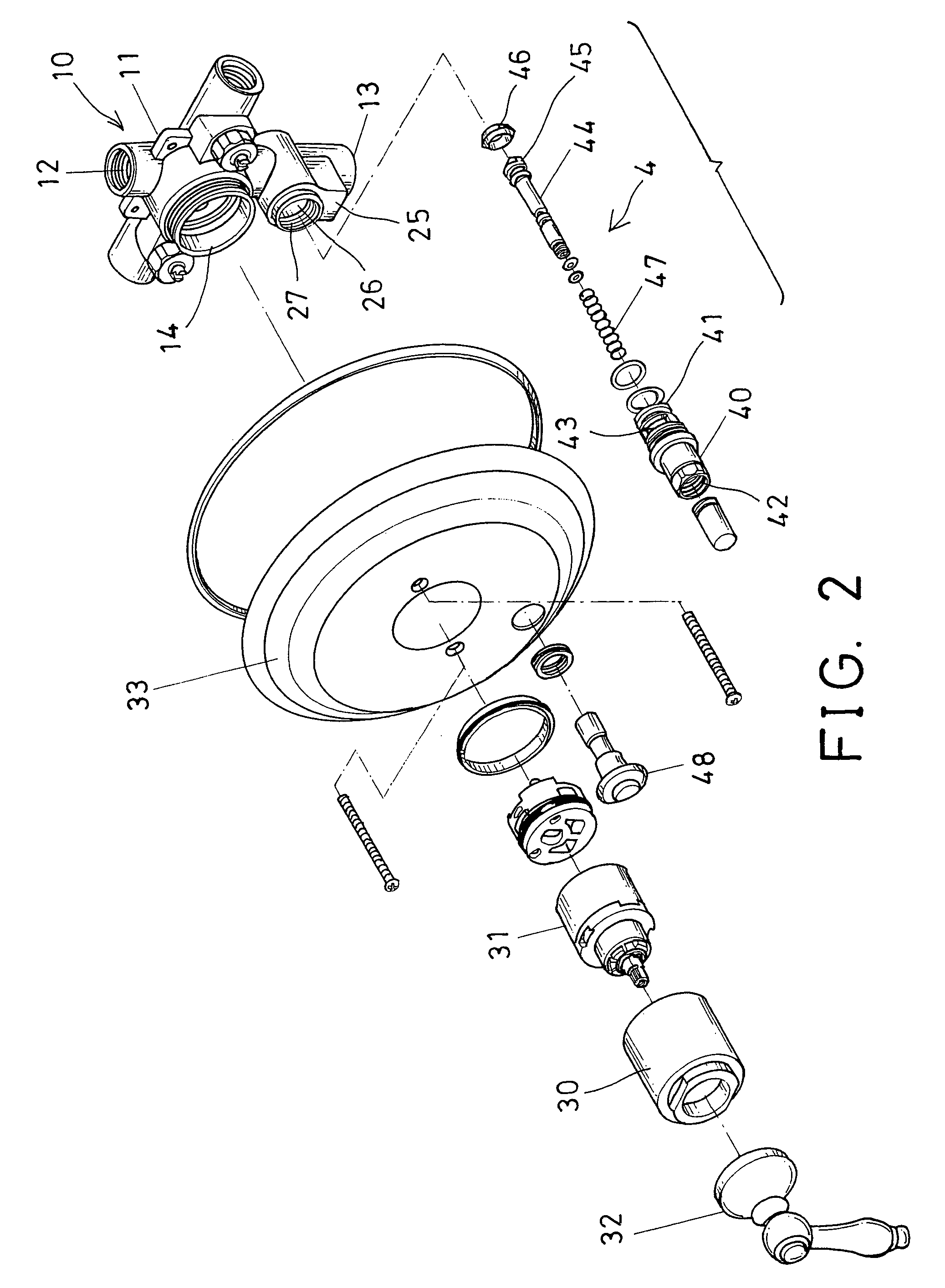
[0020]Referring next to FIGS. 2–5, and again to FIG. 1, the receptacle 11 includes the upper port 12 and the lower port 13 formed or provided in the upper and the lower portions thereof, and includes a housing 14 for receiving water and attached to an upper portion of a front wall 15 thereof which has an upper orifice 16 formed therein for communicating the housing 14 with an interior of the receptacle 11.

[0021]The receptacle 11 includes an erected or vertical partition 17 disposed in the interior thereof, to separate the interior thereof into a front chamber 18 and a rear chamber 19, in which the front chamber 18 of the r...


PUM


Abstract

A valve device includes a receptacle having an upper and a lower ports for coupling to sprayer devices, a front wall having a lower opening, an upper housing attached the front wall for allowing water to flow from the housing into the receptacle, the receptacle includes a vertical partition to separate an interior into a front and a rear chambers which are communicating with the housing and the rear chamber of the receptacle. The vertical partition includes a lower aperture formed by a valve seat. A lateral stem includes a plug slidable to engage with the valve seat of the vertical partition, or to block the lower opening of the front wall, to effectively control the water to flow out through the upper or the lower ports of the receptacle.

Description

BACKGROUND OF THE INVENTION[0001]1. Field of the Invention[0002]The present invention relates to a valve device, and more particularly to a valve device having an improved valve receptacle for allowing water to be suitably supplied upwardly to shower nozzles or to be suitably supplied downwardly to spray guns, shower nozzles, or other sprayer devices.[0003]2. Description of the Prior Art[0004]Typical valve devices or control devices for faucets may be used to control water to flow out through faucet mouths or ports only. However, in some circumstances, additional spray guns, shower nozzles, or other sprayer devices may be attached to the control devices or the faucets, for allowing the water to be selectively flown out through the additional spray guns, shower nozzles, or other sprayer devices.[0005]For example, U.S. Pat. No. 5,743,286 to Ko, and U.S. Pat. No. 5,881,754 to Wei disclose two of the typical valve devices or control devices for faucets or the like, and comprising a cont...

Claims


Application Information

Patent Timeline
Patent Type & Authority Patents(United States)
IPC IPC(8): E03C1/02F16K11/044G05D7/03
CPCE03C1/023F16K11/0445Y10T137/2685Y10T137/87249Y10T137/9464
Inventor YANG, TSAI CHEN
Owner YANG TSAI CHEN
Learn More