
Monolithic part and process for making the same

a monolithic part and process technology, applied in the field of products making processes, can solve the problems of easy predictable repeatability, etc., and achieve the effects of less weight, thinner walls, and strong and weight advantages

Inactive Publication Date: 2005-12-13
REMMELE ENG
View PDF11 Cites 16 Cited by
  • Summary
  • Abstract
  • Description
  • Claims
  • Application Information

AI Technical Summary

Benefits of technology

[0014]An advantage of the process and product of the present invention is that it provides a thinner final monolithic product which has strength and weight advantages over thicker type products produced on conventional machines. This means that designs with thinner walls and less weight may be provided and approved for use.
[0015]Another advantage of the product and process of the present invention is that the accuracy of the finished monolithic part is improved. In this instance, the process involves forming and then machining. If, as in the case of the prior art, the parts are machined, then formed, there may be a variation in how much the machined part will elongate during forming. While this can be predicted to a certain degree, the tolerance band will be wider (approximately 3-4 times minimum) over the accuracy that can be achieved by finished machining to size after the forming, and its associated elongation or other distortion, have taken place.
[0016]Another advantage of the product and process of the present invention is the weight reduction of the finished monolithic part. Weight is reduced by the elimination of fasteners, typically used to connect skin or panel members and structural framing into a single piece, and to connect such pieces to form a larger portion of a structure, for example an aircraft body. This is related to the accuracy advantage, and the inherent accuracy of final machining after forming, which will allow larger parts to be produced without undue concern for overall part accuracy.
[0018]In some embodiments, the process of the present invention comprises cold forming and high velocity machining. Forming prior to machining is a departure from the prior art, particularly when combined, in some embodiments, with the use of high velocity machining. High velocity machining has much less impact on the raw material than conventional machining. Conventional machining can release or create further stresses in the parent material. Because of this, products or parts formed, then conventionally machined may continue to distort after the machining operation. Further, this type of distortion is seldom predictable and / or repeatable. Because of this problem, the standard practice in producing monolithic parts has traditionally been machining then forming. High velocity machining on the other hand, produces better results by operating within certain developed parameters. For example, high velocity machining truly shears the material, resulting in less stress being induced into work pieces. Because of this, the distortion of the formed work piece after machining is much reduced when compared to the product of conventional machining. Also, the subsequent movement of the work piece after machining is more predictable and can be built into the process and product.
[0023]A feature of the process of the present invention is that it may be performed on five axes with minimal residual stress in the product and with generally uniform stress throughout the product.
[0026]In one embodiment, the present invention comprises a method of forming and machining wing skins (and / or aircraft body portions, airfoil skins, doors, fuselage panels, or the like) suitable for use in the aircraft industry, wherein the wing skins are machined to a final shape. In some embodiments, the product of the process, i.e., the wing skins, may have or contain integral stiffeners and ribs on the inside. In some embodiments, a suitable material for use in the process is a 7000 series aircraft aluminum alloys with a heat treatment of T7451. In some embodiments, the selected material is cold formed, meaning no heat is applied to the material during the process; in some embodiments, the material is formed and processed in a state wherein it was previously heat treated. Further, in the process of the present invention, the selected material need not be subjected to subsequent heat treatments or annealing operations, and the amount of over forming and bending back is may be selected and controlled.

Problems solved by technology

Further, this may be seldom predictable and / or repeatable.

Method used


Image

  • Monolithic part and process for making the same
  • Monolithic part and process for making the same
  • Monolithic part and process for making the same

Examples


Embodiment Construction

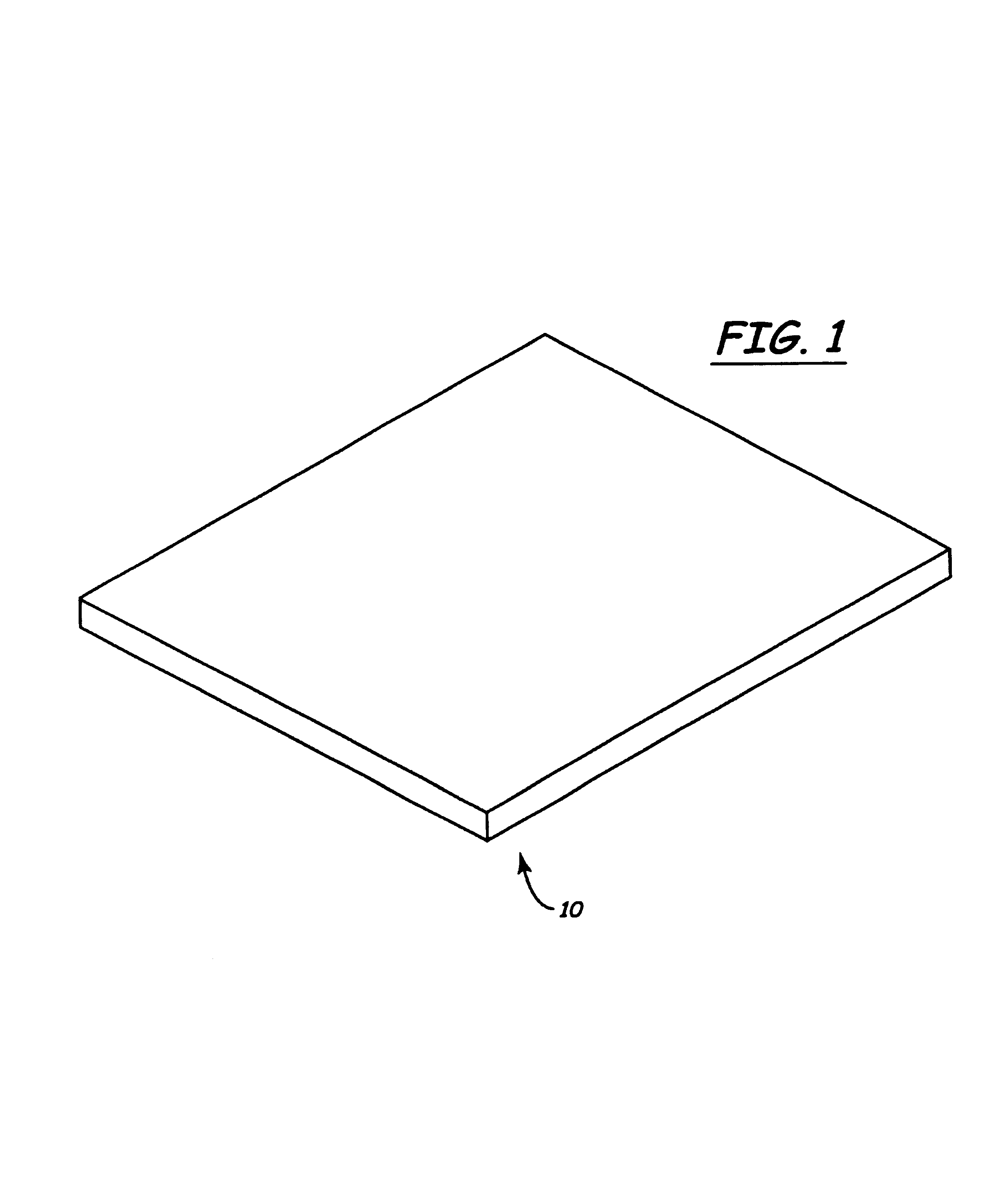
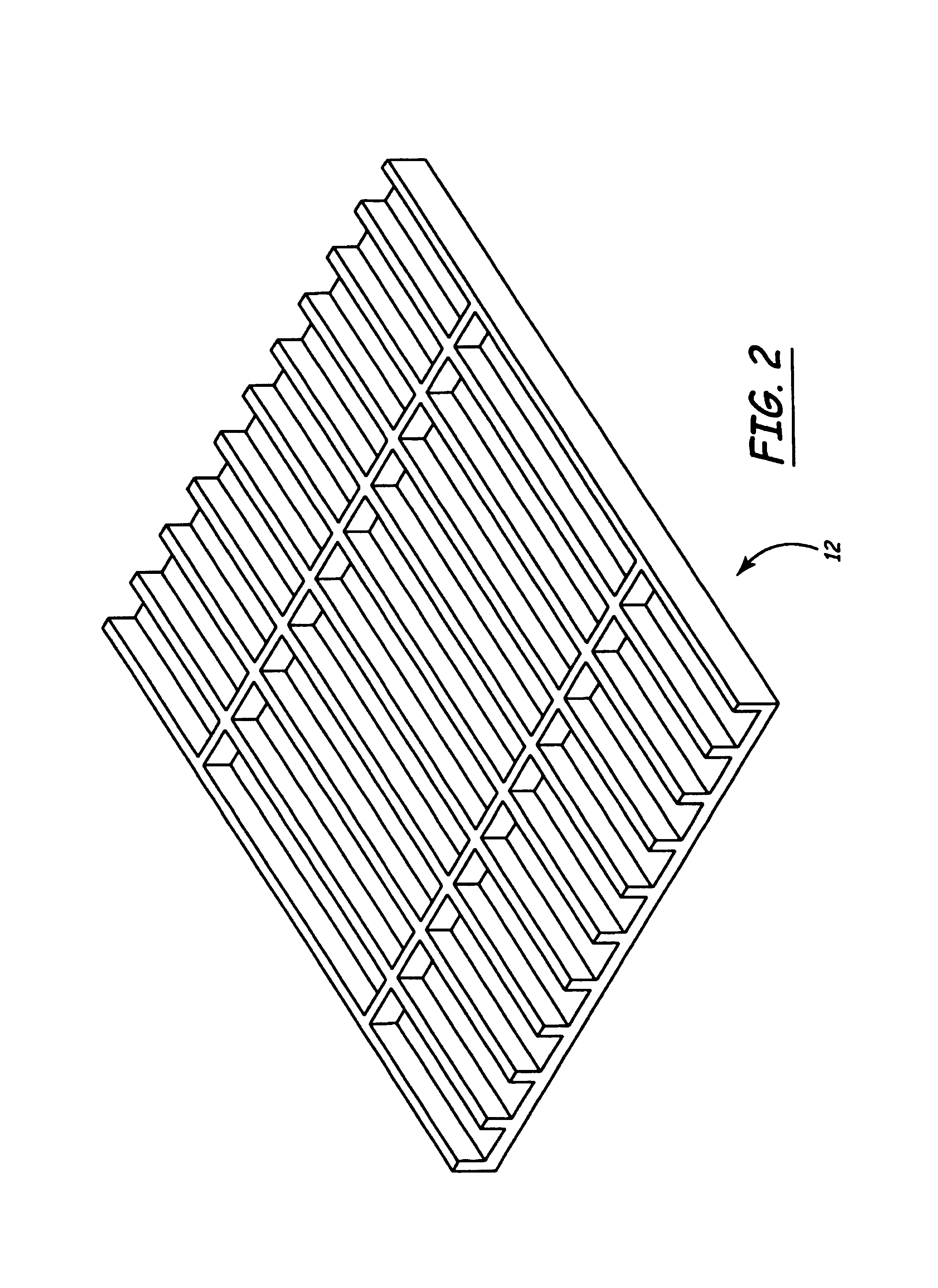
[0037]The accompanying Figures and this description depict and describe embodiments of a process or method and a product or products produced thereby in accordance with the present invention, and features, steps and components thereof. As used herein, the term “monolithic” is intended to mean comprising a substantially single unit which, in some embodiments, may be a single piece formed, composed or created without joints or seams and comprising a substantially, but not necessarily rigid, uniform whole. In some embodiments, the monolithic product of the process of the present invention may be undifferentiated, i.e., formed of a single material, and it may comprise integral structures or features such as a substantially continuous skin having an outer surface or side and an inner surface or side, and integral support members such as ribs or thickened portions comprising frame members on the inside surface of the skin. As used herein, the term “machine” (including machining, machined,...


PUM

PropertyMeasurementUnit
shapeaaaaaaaaaa
residual stressaaaaaaaaaa
structuresaaaaaaaaaa

Abstract

The present invention provides a process for producing a monolithic product wherein a piece of stock is formed, then machined. The invention encompasses a monolithic product made by the process.

Description

CROSS-REFERENCE TO RELATED APPLICATION(S)[0001]This application is a continuation of International Application No. PCT / US01 / 48176 filed on Dec. 10, 2001, which claims priority to U.S. Provisional application 60 / 254,915, filed on Dec. 12, 2000, the contents of both applications are herein incorporated by reference. The international application was published under PCT Article 21(2) in English.BACKGROUND OF THE INVENTION[0002]The present invention relates to processes for making products and to the products made by the processes. More particularly, it relates to processes and / or methods and apparatus for forming and machining a piece of stock or a work piece to produce a monolithic product, particularly a product comprising integral skin and frame or skeleton portions, and more particularly, a product suitable for use in the aircraft industry and comprising integral skin and frame portions.[0003]Currently, the majority of structural members, particularly aircraft skin and airframe str...

Claims


Application Information

Patent Timeline
Patent Type & Authority Patents(United States)
IPC IPC(8): B21J5/00B23P15/00B64C3/24
CPCB21J5/00B23P15/00B64C3/24B23P2700/01Y10T428/24174Y10T29/49995Y10T428/2457
Inventor BRYANS, PHILIP R.KELLY, JOHN C.DOERER, ALAN K.DOLEZAL, THOMAS M.
Owner REMMELE ENG
Learn More