
Passive gas flow management and filtration device for use in an excimer or transverse discharge laser

a technology of gas flow management and filtration device, which is applied in the direction of laser details, active medium material, optical resonator shape and construction, etc., can solve the problems of significant reduction in the power of the light beam discharged from the laser housing, interference with proper laser operation, and relatively complex systems. , to achieve the effect of efficient gas flow

Inactive Publication Date: 2005-12-06
AMO MFG USA INC
View PDF16 Cites 5 Cited by
  • Summary
  • Abstract
  • Description
  • Claims
  • Application Information

AI Technical Summary

Benefits of technology

"The present invention relates to laser systems and methods for filtering particles and managing gas flow. The invention provides a laser apparatus with an elongated laser chamber and an electrode structure, which includes an elongate baffle disposed within the chamber. The baffle is designed to arrest a plurality of particles generated within the chamber during laser operation. The baffle can be made of open-celled foam or metal foam, and it helps filter particles and manage gas flow within the chamber. The laser apparatus may also include a gas circulation system for circulating gas within the chamber and a baffle system for directing the gas towards the electrode structure and providing a non-turbulent gas flow around the electrode structure ends. The invention also provides methods for filtering particles from a gas in a laser apparatus by inserting an open-celled baffle system into the chamber and engaging the gas circulation system to circulate the gas within the chamber. The baffle system helps smooth a gas flow pattern and reduces misfire problems or other discharge non-uniformities. The technical effects of the invention include improved laser performance and reduced gas flow problems."

Problems solved by technology

Over time, the generated dust particles coat the surfaces of internal laser components and can interfere with proper laser operation.
Moreover, the dust particles can accumulate on the optic elements, resulting in potentially significant reduction in the power of the light beam discharged from the laser housing.
Such systems, however, are relatively complex with respect to the assembly of structural components and related circulation of the lasing gas to and from the laser housing.
Moreover, external filtration devices, depending on the circulation velocities, can have a shearing effect on the lasing gas, thus heating the gas, an undesirable effect particularly in excimer or transverse discharge laser systems.

Method used


Image

  • Passive gas flow management and filtration device for use in an excimer or transverse discharge laser
  • Passive gas flow management and filtration device for use in an excimer or transverse discharge laser
  • Passive gas flow management and filtration device for use in an excimer or transverse discharge laser

Examples


Embodiment Construction

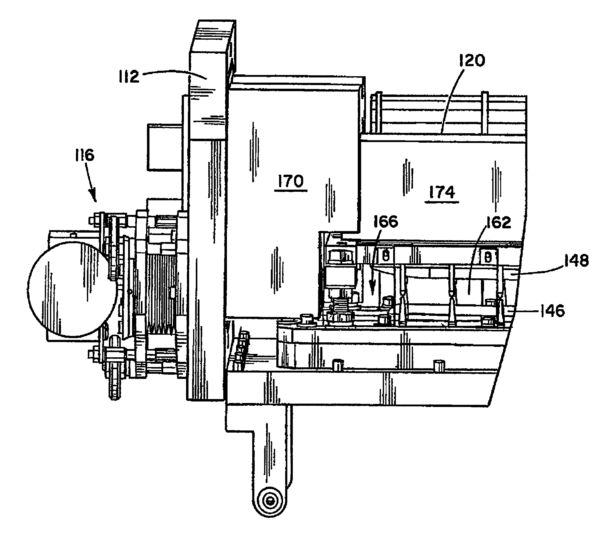
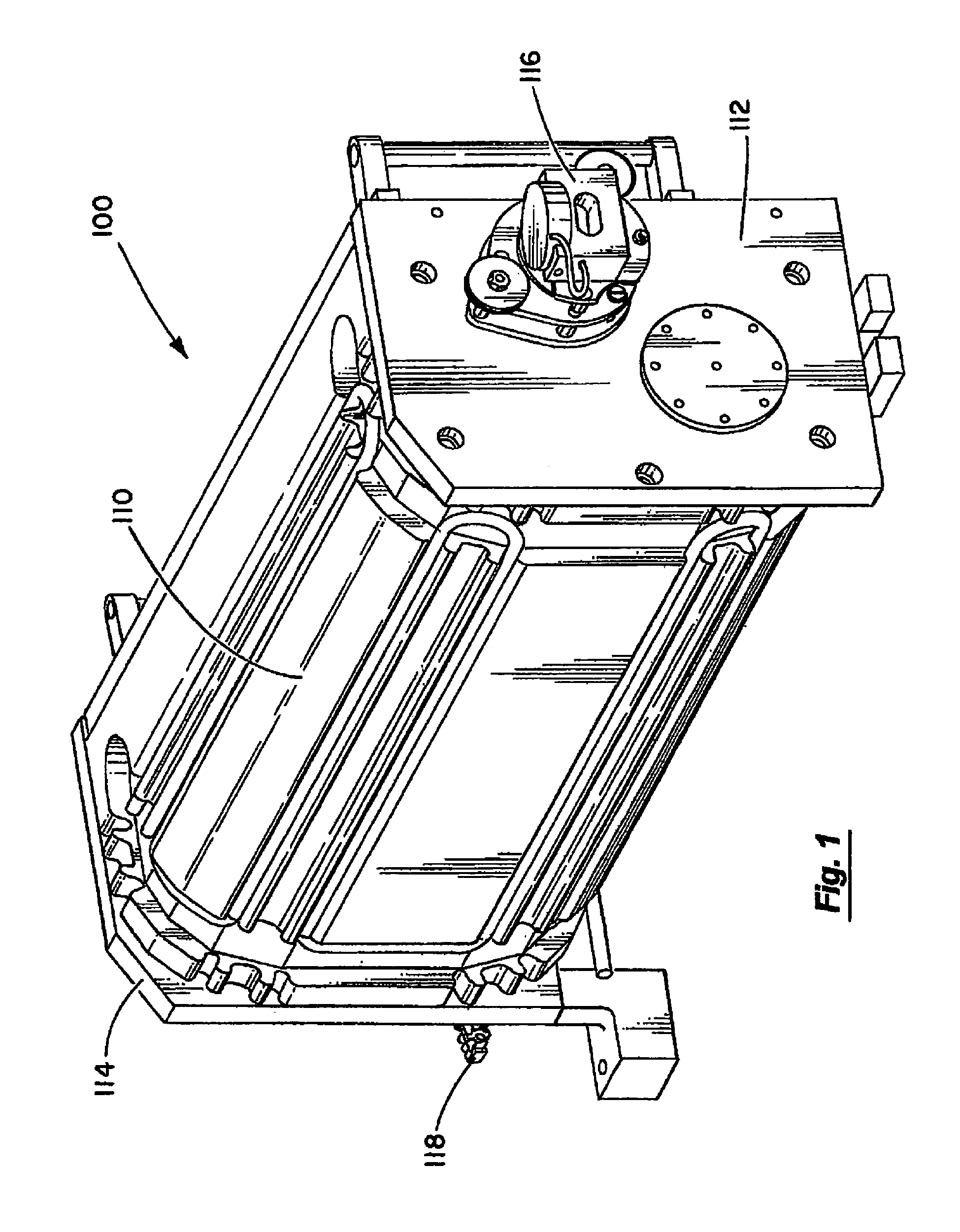
[0026]The present invention provides exemplary systems and methods for filtering particles and assisting gas flow management within laser systems. One embodiment of the present invention is depicted in FIG. 1, showing a laser apparatus 100 for use in a laser system. Laser apparatus 100 includes a casing 110 coupled to a first end plate 112 and a second end plate 114. Casing 110 and end plates 112, 114 help define a laser chamber gas containment cavity 130 within apparatus 100 (see FIG. 2). Laser apparatus 100 includes an optics package 116 and its associated mirror assembly 158 disposed at ends 112 and 114, respectively. Apparatus further includes a power connector 118 for coupling a laser fan motor 122 to an electrical power source.

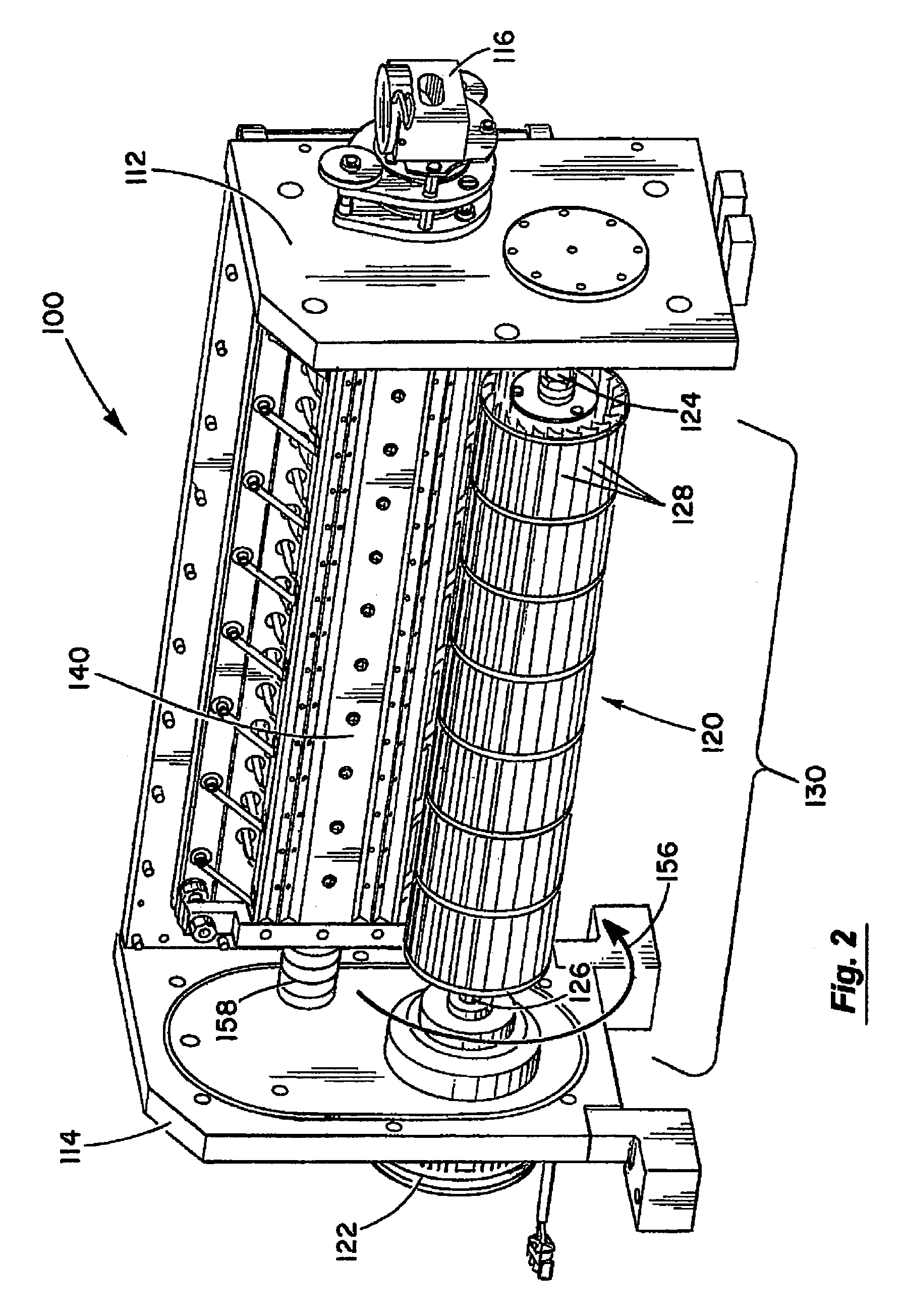
[0027]FIG. 2 depicts laser apparatus 100 without casing 110, thereby revealing a gas circulation device 120 and an electrode structure 140 enclosed within laser chamber cavity 130. In one embodiment, gas circulation device 120 is a rotary fan having a pl...


PUM


Abstract

The present invention provides systems and methods for filtering particles and assisting gas flow management within laser systems. In one embodiment, a laser apparatus (100) includes an elongate laser chamber defining a chamber cavity (130) and an electrode structure (140) disposed therein. The electrode structure includes an anode (148) spaced apart from a cathode (146). The laser includes an elongate baffle (174) disposed in the laser chamber. The baffle is adapted to arrest a plurality of particles generated within the chamber. In this manner, the baffle operates as a passive filtration system to help filter particles generated within the chamber during laser operation, and may further provide gas flow management capabilities.

Description

BACKGROUND OF THE INVENTION[0001]The present invention relates generally to laser systems, and more specifically, to systems and methods for filtering particles and assisting gas flow management within laser systems.[0002]Gas discharge lasers are generally known in the art wherein a lasing gas is excited by an electrical power source to generate a relatively coherent discharge of light. In a typical configuration, the lasing gas is contained within a substantially closed vessel or housing having a laser discharge zone defined therein between a pair of main laser electrodes. The lasing gas is excited by applying a relatively large voltage, resulting in the generation of light which can be directed and focused through appropriate optic elements to provide a narrow and coherent beam. The laser is normally operated or fired in a pulsed manner by connecting a main electrode circuit to the electrical power source at a selected operating frequency. A circulation fan is commonly provided wi...

Claims


Application Information

Patent Timeline
Patent Type & Authority Patents(United States)
IPC IPC(8): H01SH01S3/036H01S3/22H01S3/223
CPCH01S3/036
Inventor BLIVEN, BRIANTURNQUIST, DAVID
Owner AMO MFG USA INC
Learn More