


Quick Research
Generate reliable direction feasibility study reports for your R&D in just a few steps.

Technical Q&A
Discover and master advanced knowledge NOW. Basics, ideas, possibilities, all at once.

Find Solutions
As an expert in R&D theories, this can generate solutions to your technical problems instantly.

Evaluate Feasibility
Analyze your overall solution with one click, know your potential R&D risks in advance.

Monitor Landscape
Get weekly tech updates, stay abreast of the latest tech innovations and key insights.
Antenna device and wireless communication apparatus using the same
a wireless communication and antenna element technology, applied in the direction of radiating elements, elongated active elements, resonance antennas, etc., can solve the problems of inability to constitute an antenna device, and inability to assemble antenna elements in their current state. to achieve the effect of convenient mounting
- Summary
- Abstract
- Description
- Claims
- Application Information
AI Technical Summary
Benefits of technology
Problems solved by technology
Method used
Image

Examples
first embodiment
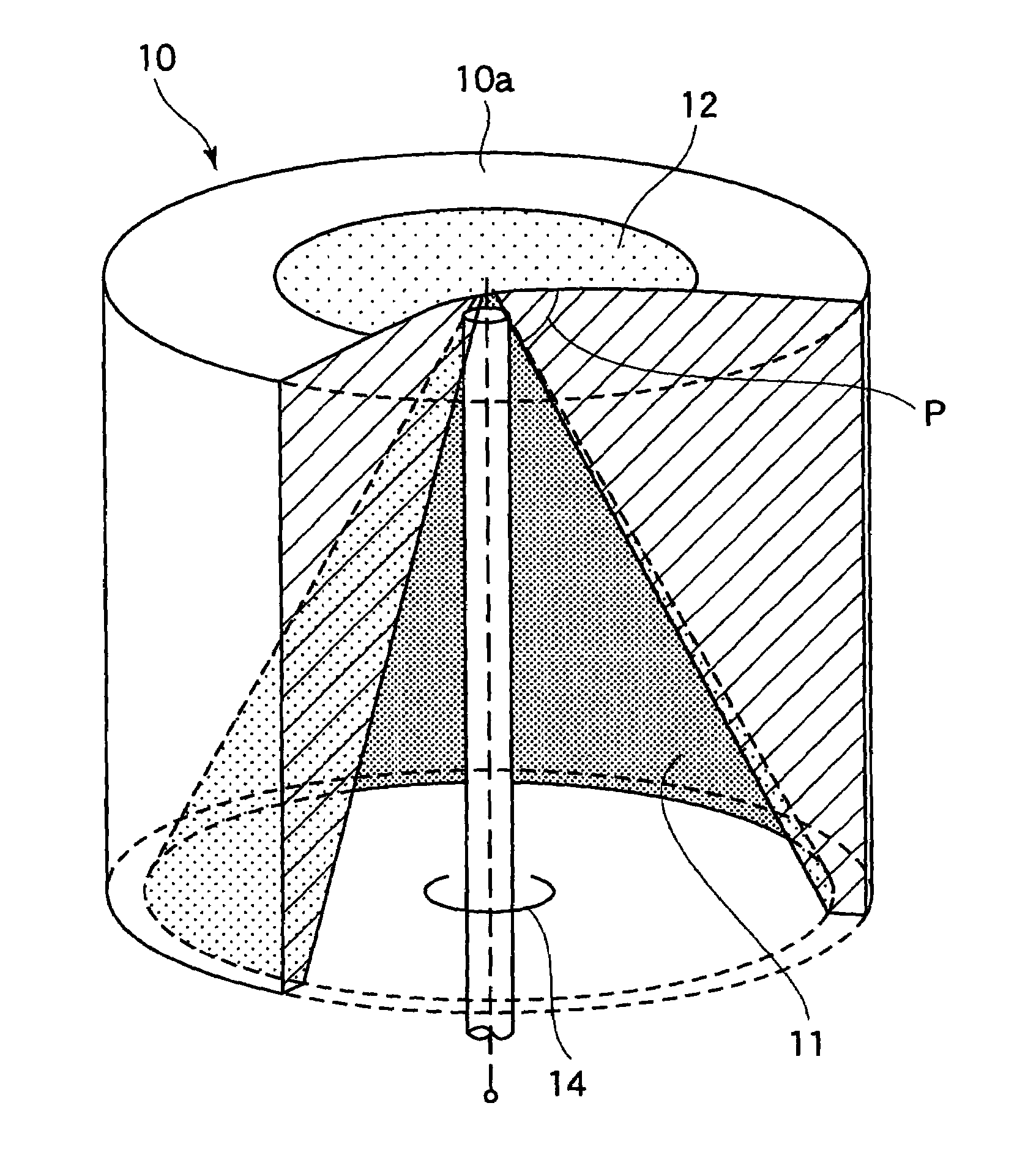
[0040]Now, referring to FIG. 6, description will proceed to an antenna device according to the present invention. As illustrated in FIG. 6, the antenna device 10 according to this embodiment forms a discone antenna and comprises a pole-shaped base member 10a which is composed of dielectric material. The pole-shaped base member 10a has a cone-shaped inner space formed therein. In an inside surface of the pole-shaped base member 10a, a first antenna element 11 is formed by patterning a metal conductor layer. Further, on a plain surface facing the outside of the pole-shaped base member 10a, a second antenna element 12 is formed also by circularly patterning a metal conductor layer at the side of a top of the first antenna element 11 with a predetermined space being kept between the top of the first antenna element 11 and the second antenna element 12. The first antenna element 11 and the second antenna element 12 are located with respective rotation central axes thereof being correspon...
third embodiment
[0050]As illustrated in FIG. 8, the antenna device 10 constitutes a biconical antenna. The antenna device 10 comprises a pole-shaped base member 10a, a first antenna element 11 and a second antenna element 12. Two conical inner spaces are formed in the pole-shaped base member 10a with respective rotation central axes thereof being corresponding with each other and with respective tops thereof facing oppositely to each other. Further, the first antenna element 11 is formed in an inner surface of one of the two conical inner spaces while the second antenna element 12 is formed in an inner surface of another one of the two conical inner spaces. Besides, in the antenna device 10 illustrated in FIG. 8, signals are supplied by the tops of the first antenna element 11 and the second antenna element 12 as a feeding point P.
fourth embodiment
[0051]Next, as illustrated in FIG. 9, the antenna device 10 constitutes a Brown antenna. The antenna device 10 comprises a pole-shaped base member 10a, a first antenna element 11 and a second antenna element 12. As illustrated in FIG. 9, a conical inner space is formed in the pole-shaped base member 10a. The first antenna element 11 is formed in the conical inner space. Further, a thrender pole-shaped hole is formed in the pole-shaped base member 10a with a rotation axis of the thrender pole-shaped hole is corresponding with that of the first antenna element 11. The second antenna element 12 is formed in an inner surface of the thrender pole-shaped hole by patterning a metal conductor layer. Besides, in the antenna device 10 illustrated in FIG. 9, a signal is supplied by the top of the first antenna element 11 and an end of the second antenna element 12 at the side of the first antenna element 11, namely, the end of the lower side in FIG. 9, as a feeding point P.
[0052]Referring to ...
PUM
 Abstract
Description
Claims
Application Information
 - R&D Engineer
- R&D Manager
- IP Professional
- Industry Leading Data Capabilities
- Powerful AI technology
- Patent DNA Extraction
Browse by: Latest US Patents, China's latest patents, Technical Efficacy Thesaurus, Application Domain, Technology Topic, Popular Technical Reports.
© 2024 PatSnap. All rights reserved.Legal|Privacy policy|Modern Slavery Act Transparency Statement|Sitemap|About US| Contact US: help@patsnap.com