
System and method for detecting a structure failure

a technology of structure failure and detection method, which is applied in the direction of bridges, transmission monitoring, instruments, etc., can solve the problems of broken cable, easy to break, and broken cable attached to the structure, so as to and reduce the risk of fractur

Inactive Publication Date: 2005-12-06
MARSHALL ROBERT A +1
View PDF6 Cites 27 Cited by
  • Summary
  • Abstract
  • Description
  • Claims
  • Application Information

AI Technical Summary

Benefits of technology

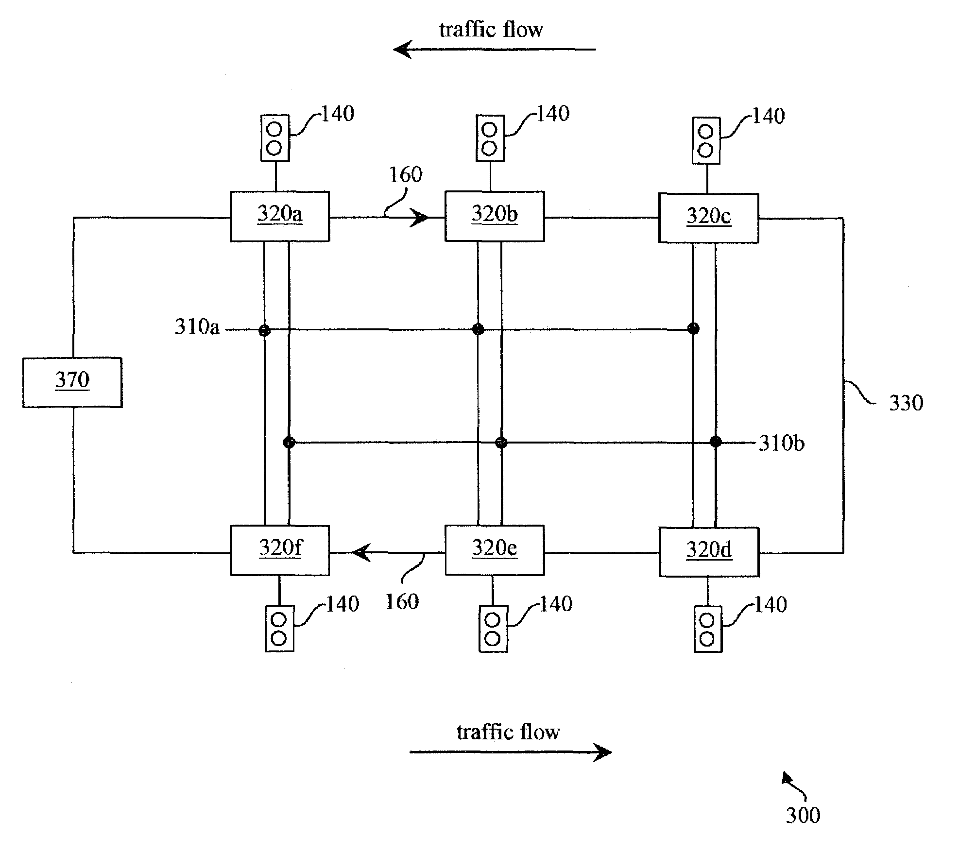
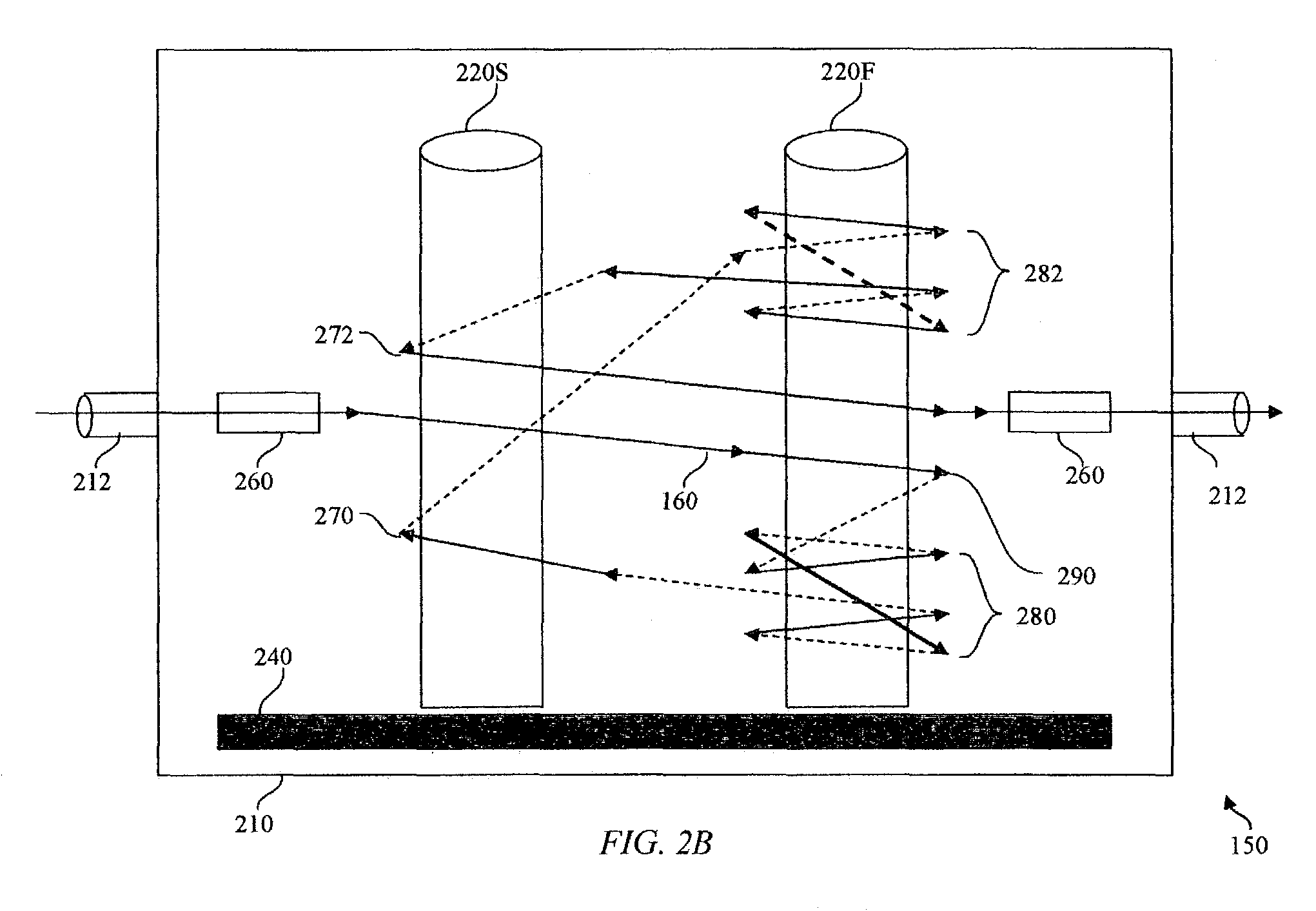
[0010]In typical fiber optic cable, aramid yarn is applied between the cable sheath and the optical fibers. The aramid provides strength to the cable as well as a low friction slip layer, required to bend the cable without breaking the glass, since inner and outer radii are different. Optical glass fiber is very brittle and easily broken with a tight bend radius or shear forces. Wrapping the fiber optic cable around a spindle will give a minimum bend radius, anchor the cable, and arrest fiber creep due to greatly increased friction caused by the pressure of pulling the fiber around a corner. Tensile strength of a typical optical fiber is approximately 20 pounds. The tensile strength of a fiber optic cable is typically greater than 200 pounds. Spindles have no sharp edges to damage the fiber when tension is applied during normal use. Optionally, the sheath and aramid yarn may be severed, which will reduce the force on the spindles by reducing the tensile strength of the cable and will reduce slippage of the fibers within the sheath.
[0011]Typically fiber optic cable stretches about 0.3% of the length of the cable before the cable breaks. Significant variations in stretch exist between various cable models and manufacturers. The amount of elongation of the cable produced by structural collapse is limited by the distance the structure is capable of falling. Therefore, the structure must be divided into segments to ensure the cable elongation of a segment caused by the falling structure is greater than the elastic modulus of the optical fiber. This is especially important for longer structures, such as causeways. Each segment is terminated at both ends by a cable anchor. Otherwise, it is possible, but by no means guaranteed, for the bridge to collapse and come to rest on top of an unbroken but stretched fiber. Each fiber segment may cross multiple expansion joints. To provide additional assurance, the fiber may also be pre-stretched. This reduces the amount of bridge displacement and cable elongation required to break the cable. Alternatively, this increased sensitivity may be traded for an increased distance between cable anchors, reducing the number of cable anchors required.
[0012]The controller may incorporate the signal source and signal detector. The controller generates and responds to only modulated data signals. This prevents environmental noise, such as sunlight entering a broken fiber, from masking an alarm. The absence of modulated light arrival at the far end indicates a failure of the structure. On detection of a structural failure, a user indicator, such as a red traffic light, is activated.
[0013]The fiber may be segmented such that one or more controllers are located midspan on the structure. Midspan controllers allow for shorter pulls of fiber optic cable into a conduit attached to the structure. One or more user indicators may be coupled to one controller.
[0014]Energy storage may be provided at each controller or at each user indicator. The battery supplies electricity to each user indicator only when the indicator is active. Key advantages include that the electric power conductors may be sized to handle the relatively small quiescent load of the controller and a slow battery charge, rather than the full power of all user indicators; and any electrical fault in the power wiring introduced during bridge failure will not unnecessarily disable any user indicators when functionality is most required. Specifically, an event such as an earthquake may cause multiple failures on a structure, disabling utility power to user indicators located between the multiple failures, which need to be on. The controller may also report battery status and perform battery tests.

Problems solved by technology

When the structure fails, the cable attached to the structure is also broken.
The cable breaks due to exceeding the elastic modulus of the cable, caused by elongation of the distance between the anti-slip cable anchors, as a result of the failing of the structure.
Optical glass fiber is very brittle and easily broken with a tight bend radius or shear forces.
The amount of elongation of the cable produced by structural collapse is limited by the distance the structure is capable of falling.
Otherwise, it is possible, but by no means guaranteed, for the bridge to collapse and come to rest on top of an unbroken but stretched fiber.

Method used


Image

  • System and method for detecting a structure failure
  • System and method for detecting a structure failure
  • System and method for detecting a structure failure

Examples


Embodiment Construction

[0023]Embodiments of the present invention and their advantages are best understood by referring to FIGS. 1 through 4 of the drawings, in which like numerals refer to like parts.

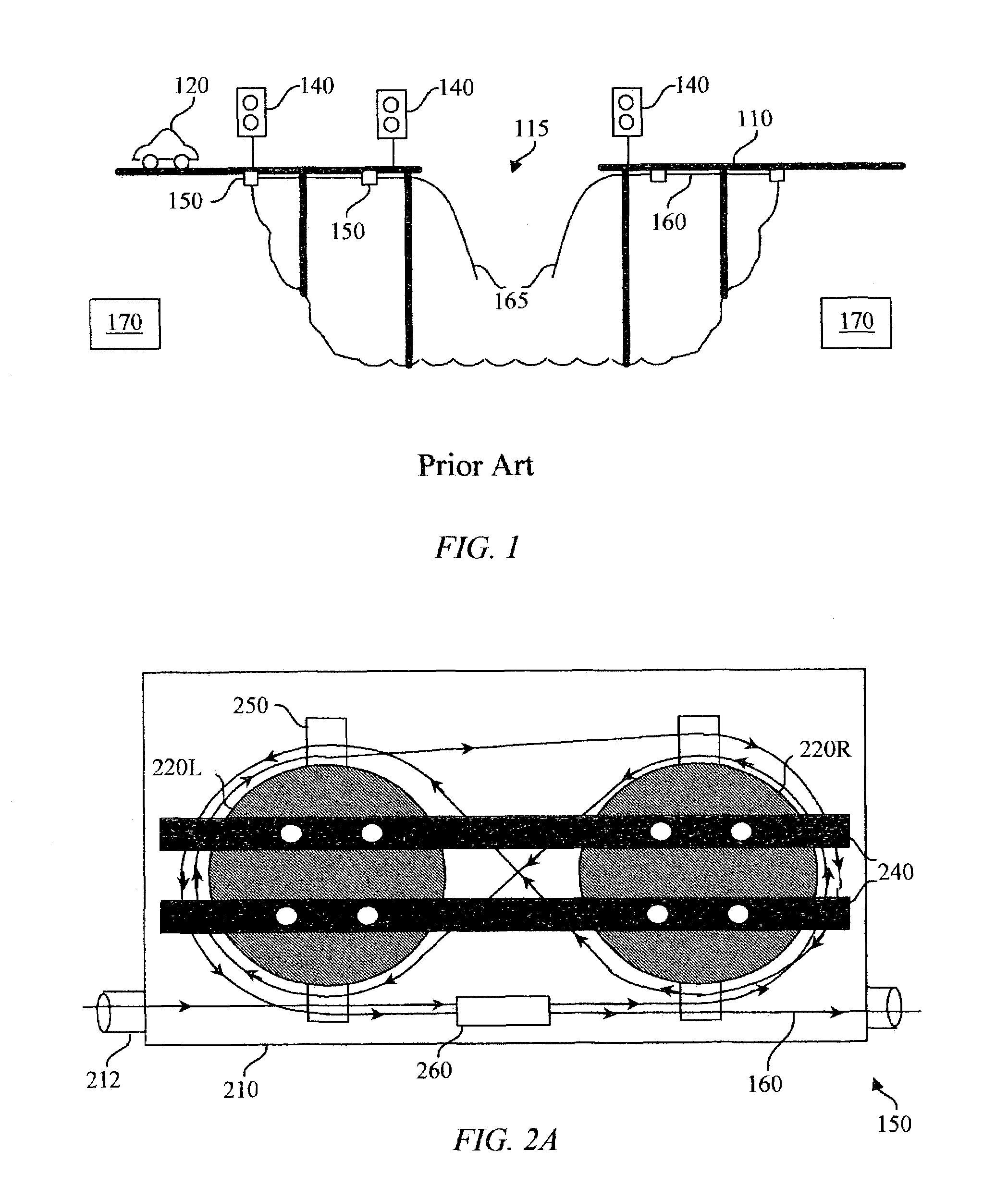
[0024]FIG. 1 is an elevation view illustrating prior art of a concrete bridge causeway with a failed span. Bridge 110 at some time may have a failed bridge span 115 caused by collision by a boat or barge. Approaching vehicle 120 may have no means for becoming aware of failed bridge span 115 due to poor lighting conditions (night, sun near the horizon, or road glare) or due to a low viewing angle. Approaching vehicle 120 may eventually become aware of a bridge failure which happened minutes or even hours before, but have insufficient stopping distance due to travel at highway speeds. When approaching vehicle 120 careens off of failed bridge span 115 there is a loss of property and a likely loss of life. Approaching vehicle 120 may include an automobile, bus, truck, train, bicycle, motorcycle, or pedestrian.

[0...


PUM


Abstract

A system for quickly and reliably detecting a failed structure includes a signal source, a cable attached to the structure, an anti-slip cable anchor, a signal detector, and user indicator. When the structure fails, the cable attached to the structure is also broken. The user indicator is operable to display the status of the cable. The cable breaks due to exceeding the elastic modulus of the cable, caused by elongation of the distance between two fixed points caused by the failing structure. Electric power must be provided to each signal source, signal detector and user indicator.

Description

TECHNICAL FIELD OF THE INVENTION[0001]This invention relates generally to the field of transportation safety and, more specifically, to warning of a catastrophic structural failure by elongation of the path between two points.BACKGROUND OF THE INVENTION[0002]Any number of hazards may cause a structure, such as a span of a bridge or causeway, to fail. Some common hazards include collision by a boat, barge or train, earthquake, earth movement, flood, fatigue, aging or malicious activity.[0003]Unfortunately, the consequences of such a failed bridge frequently include loss of life and property. Much of this loss of life or property is from vehicles nowhere near the affected portion of the structure at the time of failure. The vehicle operator is simply not aware of the hazard ahead and proceeds to drive over the edge of the failed bridge.[0004]In many cases, the viewing angle of a failed bridge span limits the distance to which a motorist can visually see any trouble ahead. By the time ...

Claims


Application Information

Patent Timeline
IPC IPC(8): G08B21/00G08B21/10
CPCG08B21/10
Inventor MARSHALL, ROBERT AMARSHALL, FRED R.
Owner MARSHALL ROBERT A
Learn More