Hydraulic drive system and improved control valve assembly therefor

a technology of hydraulic drive system and control valve assembly, which is applied in the direction of fluid couplings, servomotors, hybrid vehicles, etc., can solve the problems of overall system performance, inability to meet the needs of users, and inability to perform useful functions, etc., to achieve fast response time, small pressure drop, and large flow volume

Inactive Publication Date: 2005-12-06
EATON CORP
View PDF4 Cites 74 Cited by
  • Summary
  • Abstract
  • Description
  • Claims
  • Application Information

AI Technical Summary

Benefits of technology

[0007]Accordingly, it is an object of the present invention to provide an improved control valve assembly for use in a hydraulic system, wherein the control valve assembly is able to control relatively large flow volumes at a very fast response time, but with a very small pressure drop across the control valve assembly, and very low quiescent flows.

Problems solved by technology

For example, during extensive time periods when the pump-motor unit is at zero displacement, and is de-clutched from the drive-line, it would not be acceptable, in terms of overall system efficiency, to have a continuous pilot flow of pressurized fluid flowing from the mode valve assembly to the system reservoir, hydraulic horsepower, but with no useful function being performed during that time period.
However, it would also not be acceptable, in terms of overall system performance, and specifically, in terms of “responsiveness” (speed of operation), to have a mode control valve in which its opening and closing function would require (at the time its operational state must change) that the system wait for some sort of pilot signal to build sufficient pressure in a chamber to be able to move the main mode valve member between its open and closed positions.
Also, because the hydraulic drive system of the invention serves as the main drive for the vehicle, at least during a brief period of time, the control valve assembly must be able to control the flow of a relatively large flow volume, but, a large flow being metered generally implies large pressure drops across the particular valve element, and as noted previously, such large pressure drops in the system would make the overall system unacceptable, in terms of system efficiency.

Method used


Image

  • Hydraulic drive system and improved control valve assembly therefor
  • Hydraulic drive system and improved control valve assembly therefor
  • Hydraulic drive system and improved control valve assembly therefor

Examples


Embodiment Construction

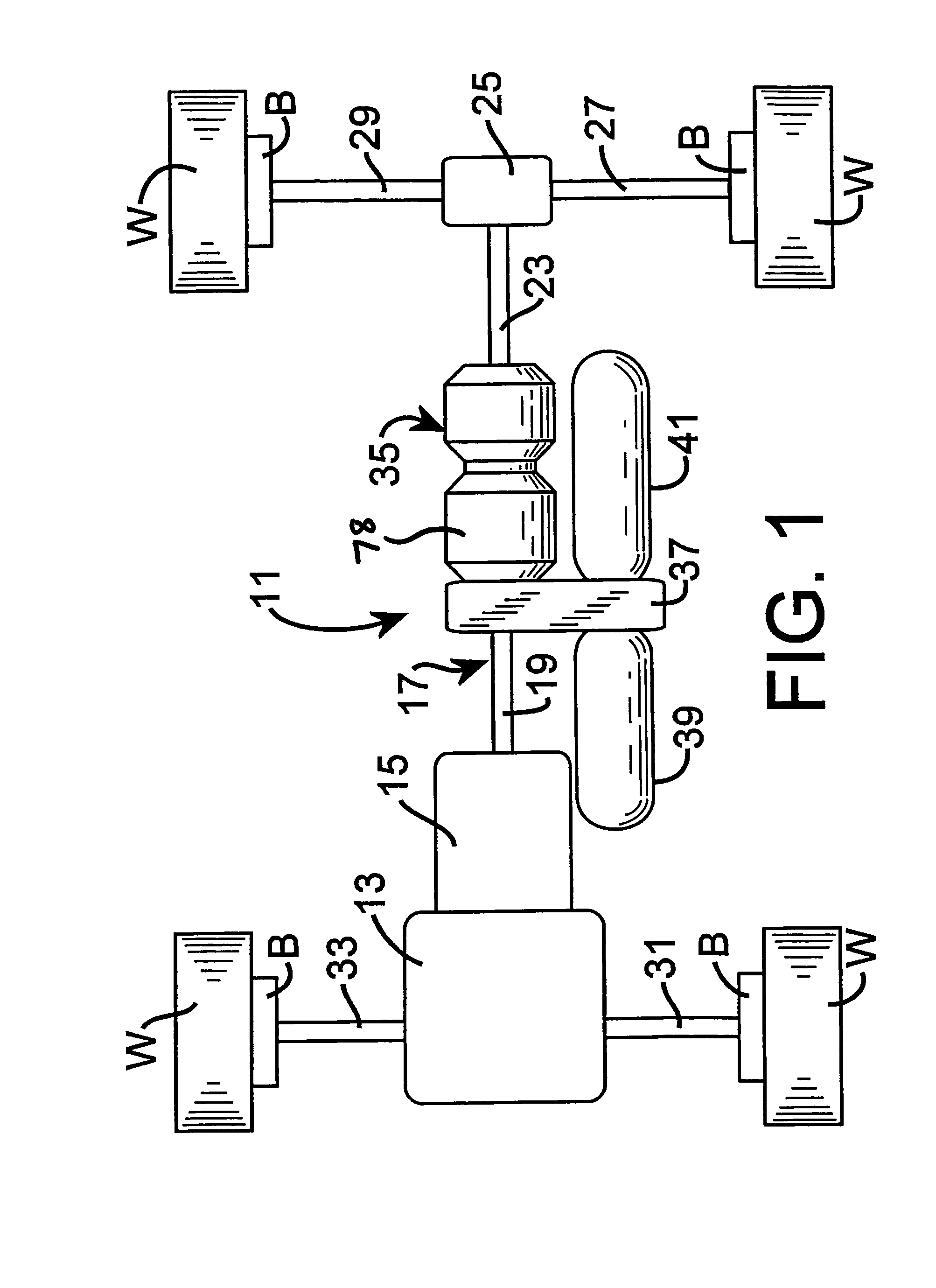
[0017]Referring now to the drawings, which are not intended to limit the invention, FIG. 1 illustrates a vehicle drive system of the type for which the hydraulic drive system of the present invention is especially well suited. The vehicle system shown schematically in FIG. 1 has four drive wheels W, although it should be understood that the present invention is not limited to a vehicle having four-wheel drive (or even four drive wheels), but could also be used with a vehicle having only two-wheel drive, and in that case, the two drive wheels could be either rear drive wheels or front drive wheels. Operably associated with each of the drive wheels W could be a conventional type of wheel brake B, the details of which form no part of the present invention, and the wheel brakes B will be referred to only briefly hereinafter. Preferably, the wheel brakes B are part of an overall EHB (electro-hydraulic brake) system, of the type which is just now becoming well known to those skilled in th...


PUM


Abstract

A control valve assembly (43) for use in a system in which a pump-motor unit (35) can either receive drive torque from a drive-line (17) or transmit torque thereto. The system includes a high pressure accumulator (41) and the control valve assembly is disposed between the pump-motor unit and the accumulator, and includes a mode valve (45) normally biased closed by pressure in a control cavity (89), the fluid pressure in which is controlled by a pilot valve assembly (49) in response to an electrical signal (133). A step-orifice valve (47) associated with the mode valve poppet member (79) provides a relatively larger orifice (115) into the control cavity (89) when pressure therein is high, and a relatively smaller orifice (119) into the control cavity when pressure therein is low, i.e., when the pilot valve assembly (49) is open. Thus, a large volume of flow can occur from the accumulator to the unit (35) in a motoring mode, with a relatively low pressure drop, while the poppet member is able to have softer, relatively longer opening time, but a relatively faster closing time.

Description

CROSS-REFERENCE TO RELATED APPLICATIONS[0001]This application is a continuation-in-part (CIP) of co-pending application U.S. Ser. No. 10 / 624,805, filed Jul. 22, 2003 now abandoned, in the name of Rodney V. Singh for a “Hydraulic Drive System And Improved Filter Sub-System Therefor”.BACKGROUND OF THE DISCLOSURE[0002]The present invention relates to hydraulic drive systems of the type including a pump-motor unit which operates as a pump during a portion of the vehicle operating cycle, and as a motor during another portion of the vehicle operating cycle. Even more particularly, the present invention relates to an improved control valve assembly (“mode” valve) for controlling the “mode” of operation of the pump-motor unit, i.e., whether the unit operates in the pumping mode or in the motoring mode.[0003]Although the mode control valve assembly of the present invention may be utilized in hydraulic systems of various types, including such drive systems which effectively serve as the prima...

Claims


Application Information

Patent Timeline
Patent Type & Authority Patents(United States)
IPC IPC(8): B60K6/12B60K17/10B60T1/10F15B1/02F15B11/02F15B13/04F15B13/042F15B13/043F15B21/14F16D31/02
CPCB60K6/12F15B1/024F15B13/0405F15B13/0426F15B13/043F15B21/14F16D31/02F16K31/406Y02T10/6208Y02T10/62A45D1/02
Inventor SINGH, RODNEY V.
Owner EATON CORP
Why Eureka
Try Eureka