
Working machine

a working machine and hybrid technology, applied in the direction of machines/engines, propulsion using engine-driven generators, electric generator control, etc., can solve the problems of reduced storage capacity, increased cost in operation, and extremely short li

Inactive Publication Date: 2005-11-29
KOBELCO CONSTR MASCH CO LTD
View PDF17 Cites 19 Cited by
  • Summary
  • Abstract
  • Description
  • Claims
  • Application Information

AI Technical Summary

Benefits of technology

The present invention provides a working machine that can operate in a hybrid manner using both electric power from an engine and stored power from a power storage means. The machine can also operate at high power for long distance traveling under certain conditions. The structural arrangement of the machine includes electric motors driven by a power generator and a power storage means, with a working device and a traveling device activated by the electric motors. The machine can operate in a normal mode or a high-output mode, with the high-output mode being carried out during high speed traveling time. The machine can also switch between a low-speed and high-speed travel mode, and a capacitor can be used as the power storage means.

Problems solved by technology

On contrary, such a battery is operated with the aid of the chemical reaction between an electrolyte and electrodes, and therefore this causes the lifetime to become extremely short, when it is used in a working machine, such as an excavator, wherein the charging / discharging is frequently repeated due to a significant variation in the load.
This eventually necessitates the exchange of the battery with high frequency, and leads to an increased cost in operation as well as to a disadvantage resulting from the environment problem due to the abandonment of batteries.
Nevertheless, a reduced storage capacity provides a rapid consumption of charges, thereby making it difficult to travel at high speed in a long distance as described above.
In this case, however, the cost of manufacturing the condensers extremely increases, along with increased complexity in the control, so that such a system is not available in the practical usage.

Method used


Image

  • Working machine
  • Working machine
  • Working machine

Examples


first embodiment (see figs.1 to 4)

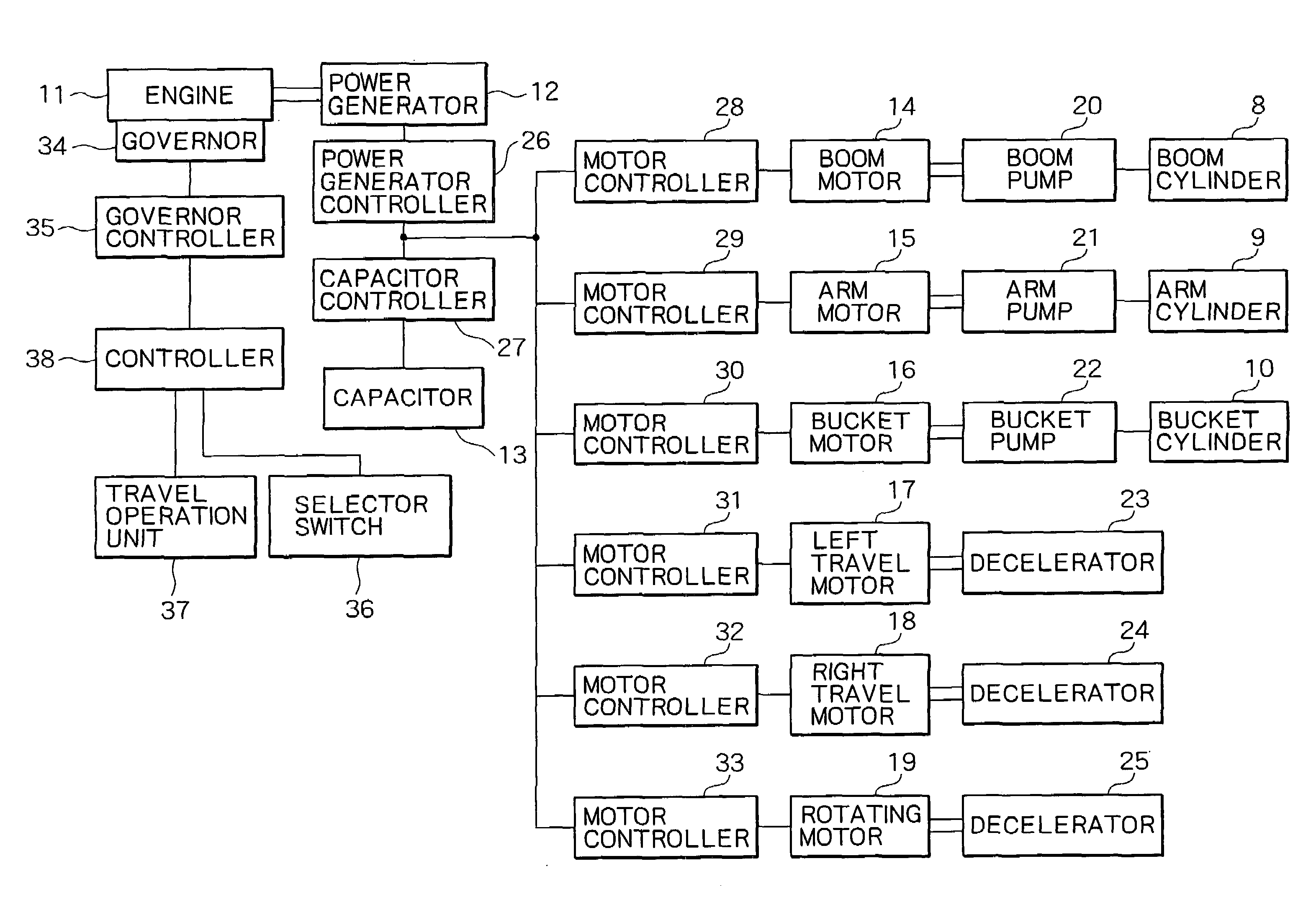
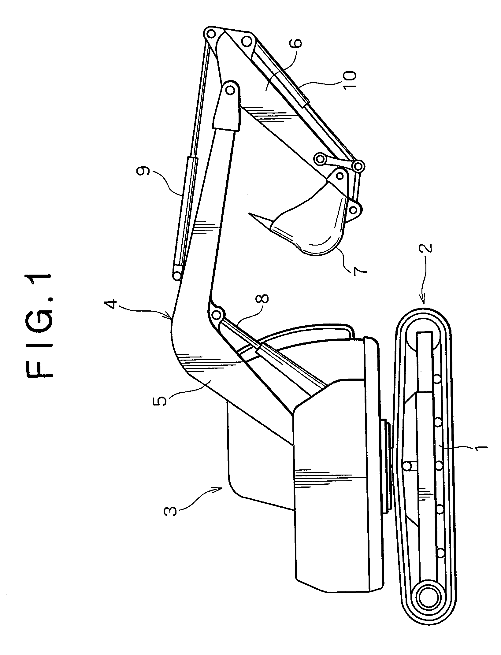
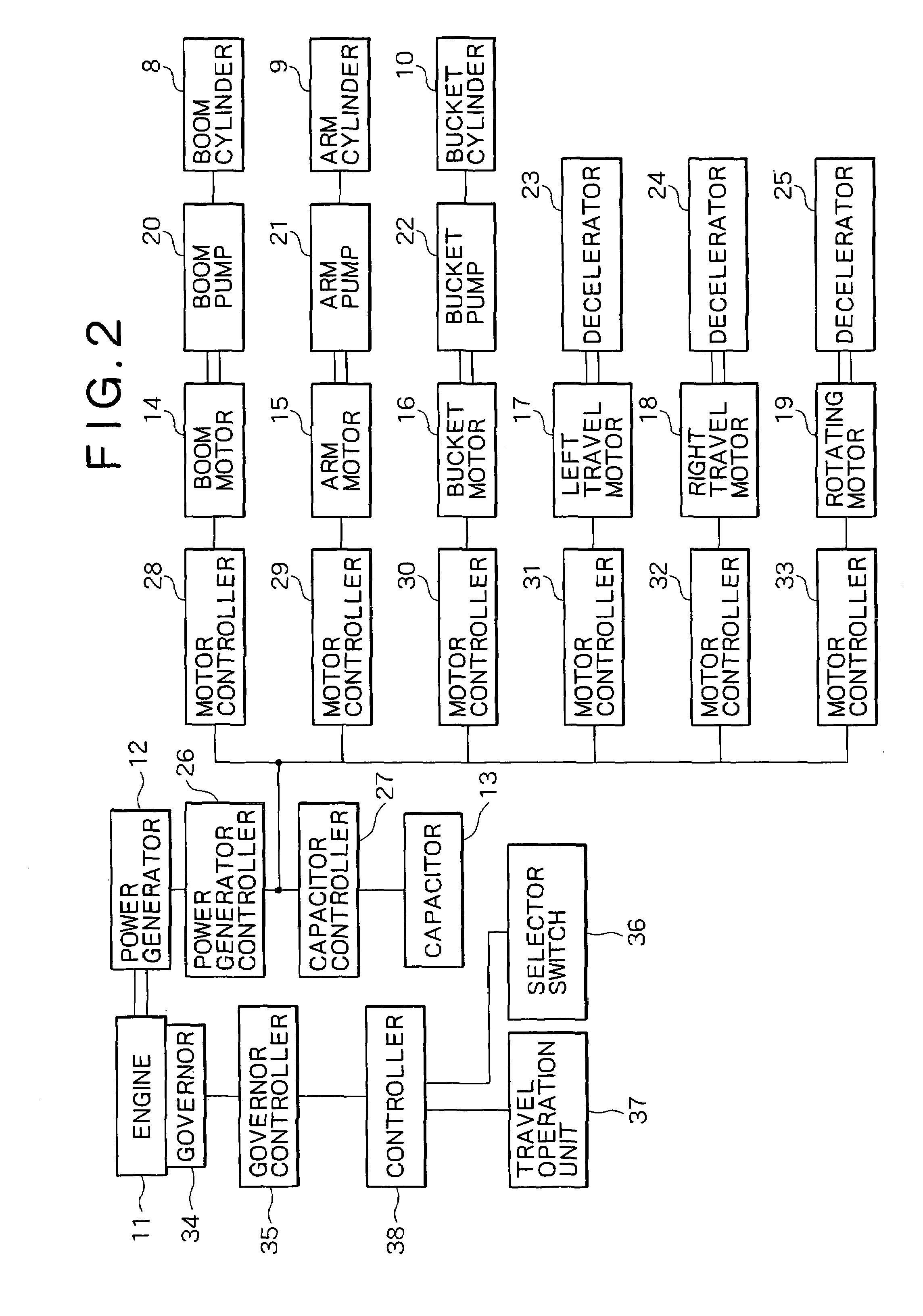
[0028]First Embodiment (See FIGS. 1 to 4)

[0029]As shown in FIG. 1, the excavator is constituted such that an upper rotating body 3 is mounted on a lower traveling body 2 which is equipped with a crawler type traveling apparatus 1 as traveling device, and that an excavating apparatus 4 as a main working apparatus or working device is mounted onto the upper rotating body 3.

[0030]In the excavating apparatus 4, an arm 6 is mounted onto an end of a boom 5 free to rise and fall, and a back hoe system bucket 7 is further mounted onto an end of the arm 6. The boom 5, arm 6 and bucket 7 are driven by a boom cylinder 8, arm cylinder 9 and bucket cylinder 10, respectively.

[0031]As a modification of the excavator, a clamshell type bucket can be employed for the bucket 7, or a griping type or vibration type crushing apparatus can be employed, instead of the bucket 7, and / or a telescopic arm can be employed for the arm 6.

[0032]As shown in FIG. 2, the upper rotating body 3 is equipped with an engi...

second embodiment (see fig.5)

[0044]Second Embodiment (See FIG. 5)

[0045]A second embodiment of the present invention will be described with regard to only the difference from the first embodiment.

[0046]In the second embodiment, an excavator is constituted such that a hydraulic pump 41 is driven by an electric motor 39 (controlled by a motor controller 40) to which a power generator 12 and a capacitor 13 are assigned as the electric power sources, and that the pressure oil from the hydraulic pump 41 is supplied to a boom cylinder 8, arm cylinder 9 and bucket cylinder as well as to a hydraulic motor 43 for left travel, a hydraulic motor 44 for right travel and a hydraulic motor 45 for rotation via control valves 42 (Although these valves are provided each of the hydraulic motor, here, it is collectively shown).

[0047]In the second embodiment, a selector switch 36 and travel operation unit 37 are also connected to a governor controller 35 via a controller 38. A switching signal from the selector switch 36 and a trav...


PUM


Abstract

A hybrid system working machine, during a normal working time, operated by a normal operation mode that the output of a power generator and the accumulated power of a capacitor are used while the engine is operated over a high-efficiency range at a low output. Switching of a selector switch to a high-speed running mode position and running operation enable long-distance and high-speed running of an increase in engine output by a high-output operation mode.

Description

TECHNICAL FIELD[0001]The present invention relates to a so-called hybrid system working machine, in which a power generator is driven by an engine, and appropriately utilizing both an electric power resulting from the generator and an electric power stored in a power storage means, electric motors are driven to activate both a working apparatus and traveling apparatus.BACKGROUND ART[0002]A hybrid system working machine is constituted such that an averaged part of the required electric power is supplied from a generator, and when the generator is deficient in the electric power to be supplied, the shortage is supplemented by the electric power stored from a power storage means, whereas when the electric power is supplied in a relatively greater amount from the generator, the surplus electric power is stored (charged) in the power storage means.[0003]Accordingly, the power storage means repeats the charging / discharging, changing the input / output in accordance with a variation in a loa...

Claims


Application Information

Patent Timeline
Patent Type & Authority Patents(United States)
IPC IPC(8): B60K6/20B60K6/28B60K6/46B60L50/15B60W10/06B60W10/08B60W10/26B60W10/30B60W20/00E02F9/20E02F9/22F02D29/06F02D41/04
CPCB60K6/28B60K6/46B60L1/003B60L1/20B60L11/005B60L11/123B60W10/06B60W10/08B60W10/26B60W10/30B60W20/00E02F9/2025E02F9/2217F02D29/06B60L2200/40B60L2260/12B60W2300/17B60W2520/10Y02T10/6217Y02T10/6286Y02T10/7022Y02T10/7077E02F9/2075E02F9/2091B60L50/40B60L50/61Y02T10/62Y02T10/70Y02T10/7072
Inventor YOSHIMATSU, HIDEAKI
Owner KOBELCO CONSTR MASCH CO LTD
Learn More