
Polymer shell bat

a polymer shell and bat technology, applied in the field of bats, can solve the problems of insufficient prior art needed bats and the increase in the cost of bats, and achieve the effects of reducing the sting of any hit on the barrel portion, reducing the cost, and being less expensiv

Inactive Publication Date: 2005-11-29
RAWLINGS SPORTING GOODS
View PDF26 Cites 36 Cited by
  • Summary
  • Abstract
  • Description
  • Claims
  • Application Information

AI Technical Summary

Benefits of technology

[0011]One advantage of the present invention is the construction of a bat with reduced cost. The current method of construction for a composite shell bat tends to run four (4) to five (5) times the cost of the construction of the present bat with a polymer shell. Thus, the present invention provides a less expensive alternative to the current shell technology. There are several materials that are being used to tweak the design of the present invention. These materials vary in density, compression strength, and flex modulus.
[0012]One advantage of the material being used is the material's characteristic to act as a natural vibration dampener. This vibration reduction helps to reduce the sting in any hits on the barrel portion.
[0013]Initially, the concept of the present invention was created to apply this shell in a fast pitch market where light weight, reduction in vibration, higher performance with durability, and lower cost were all driving factors for a bat design. However, after initial prototyping, other advantages of this technology were realized for all of the different types of bat designs.
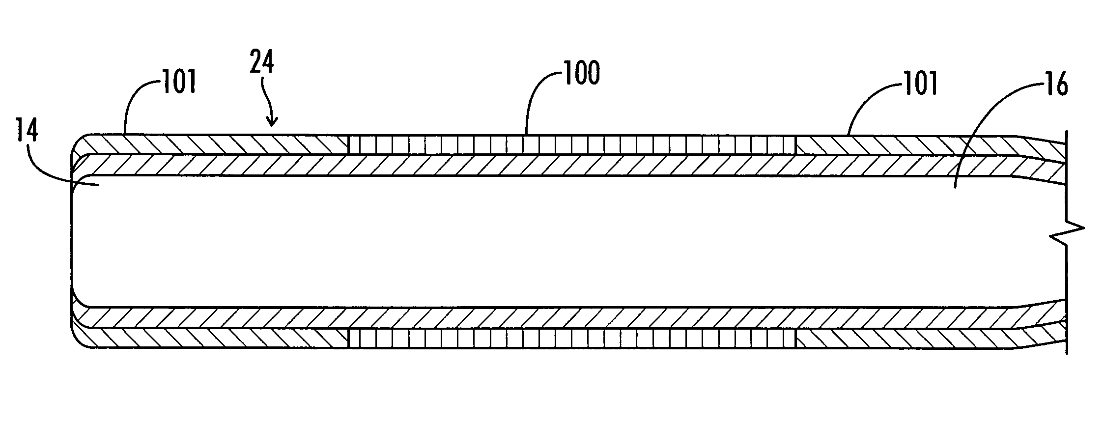
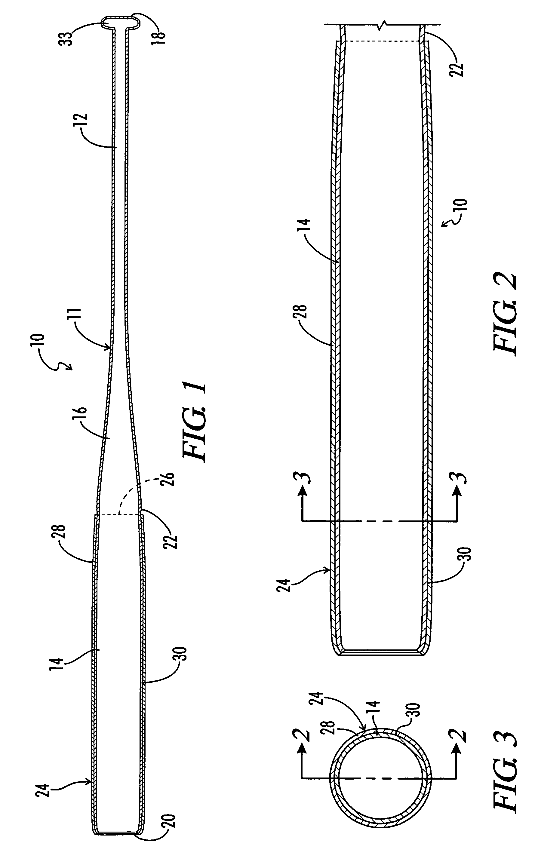
[0014]In one embodiment, the bat includes a metal frame having a polymer outer shell formed directly about the barrel portion of the bat. Preferably, the metal frame includes a handle portion, a transition portion and a barrel portion, with the metal frame having an annular step defined therein distally of the handle portion. The polymer outer shell is formed about the metal frame and has a proximal end located adjacent the annular step of the metal frame.
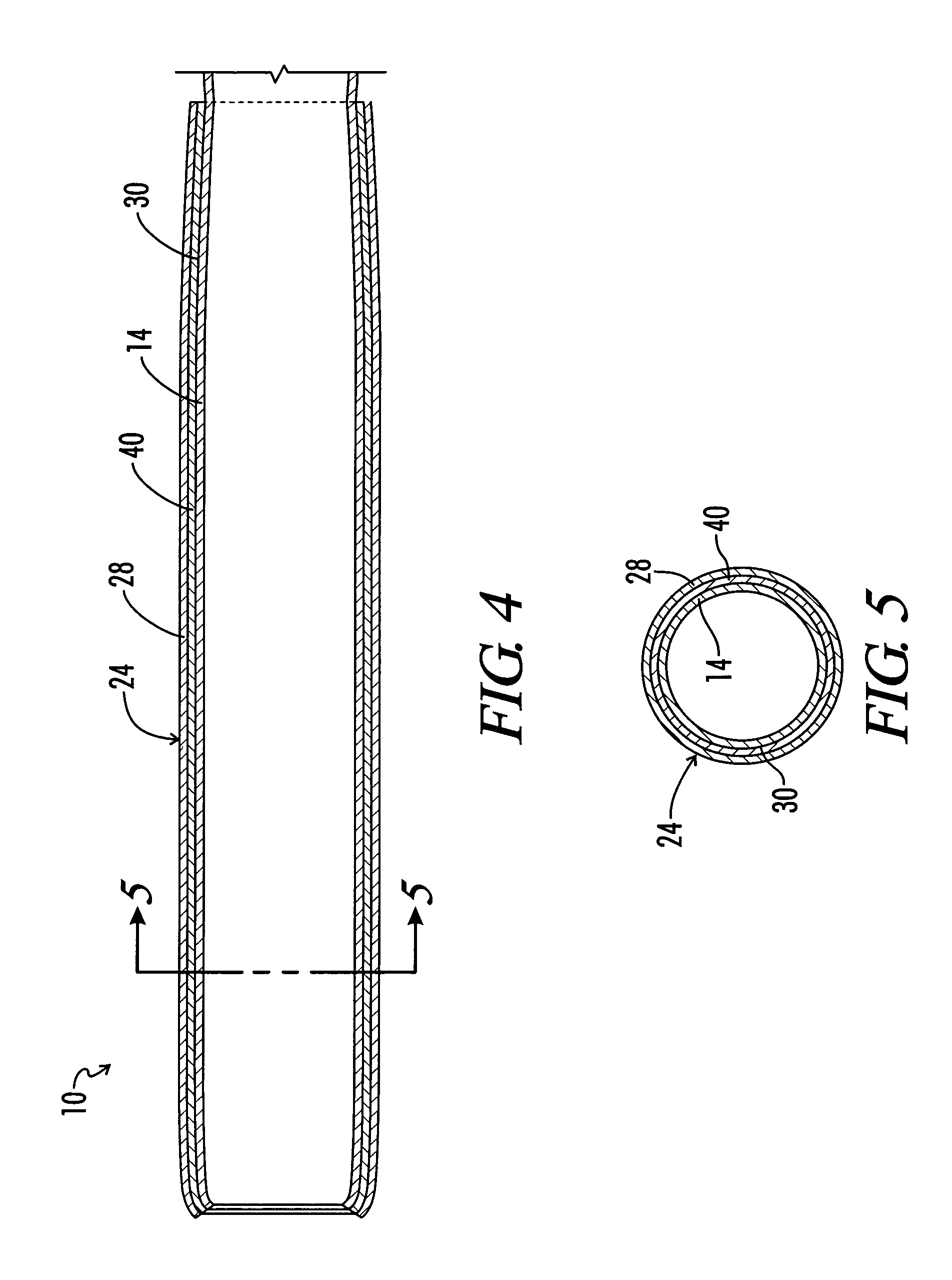
[0015]In a second embodiment of the invention, the barrel portion of the bat includes an outer metal shell formed about the barrel portion of the frame, with a polymer outer shell formed about the outer metal shell.
[0016]In still a third embodiment of the invention, a polymer outer shell is formed around only an intermediate portion of the metal frame spanning a point of maximum bending stress, so as to provide increased stiffness of the bat at the area of the point of maximum bending stress. The metal frame of the bat extends both proximally and distally from the intermediately located polymer outer shell.

Problems solved by technology

The need for high performance bats has caused bats to become more and more expensive.
This needed bat is lacking in the prior art.

Method used


Image

  • Polymer shell bat
  • Polymer shell bat
  • Polymer shell bat

Examples


second embodiment

[0049]Turning now to FIGS. 4 and 5, the invention is illustrated. In this embodiment, the barrel portion 14 of the metal bat frame 11 has received thereabout an outer metal sleeve 40 which is constructed in a manner substantially like that of Pitsenberger U.S. Pat. No. 6,053,828, the details of which are incorporated herein by reference. This external metal sleeve 40 covers the barrel portion 14 of the bat and terminates adjacent the annular step 22 so that it is substantially co-extensive with the outer polymer shell 24 seen in FIG. 1. In the embodiment of FIGS. 4 and 5, the outer polymer shell 24 is in fact formed on the outer metal shell 40.

[0050]Thus, after formation of the outer metal shell 40 about the metal bat frame 11 in a manner like that described in U.S. Pat. No. 6,053,828, the polymer outer shell 24 is formed upon the outer metal shell 40 in a manner like that just described with regard to the embodiment of FIGS. 1–3.

[0051]With the embodiment of FIGS. 4 and 5, the outer...

third embodiment

[0054]FIGS. 6 and 7 illustrate the invention wherein a polymer outer shell 48 is formed only about an intermediate portion 50 of the metal frame 11.

[0055]It will be understood that for any given design of a bat, the bat frame will have a point along its length which is subjected to a maximum bending stress when the bat is used to strike a ball. For example, the bat shown in FIG. 6 may have a point of maximum bending stress along the line x—x. For example, for a typical aluminum bat construction, the point of maximum bending stress x—x would be located a distance 51 from the proximal end 18 of the bat, which distance would typically be approximately 11 inches and would place the point of maximum bending stress x—x in the distal part of the handle portion 12 of the bat frame 11.

[0056]The present invention also envisions the selective strengthening of a metal bat by the placement of a polymer outer shell 48 only around an intermediate portion 50 of the bat frame which spans the point x...

fourth embodiment

[0079]this bat 10 is constructed with an Aluminum frame 11, and aluminum shell 40 on the outside of the aluminum frame 11 in the barrel 14 and taper 16. Polymer 24 would be applied to the barrel 14, taper 16 and handle 12 section. The aluminum could be substituted with MMC, Foam, Wood, Plastic, Titanium, Steel, or any other solid structure that will maintain a bat 10 shape.

[0080]The polymers could be either thermosets or thermoplastics. Examples of Thermosets would be Epoxy, Polyester, and Polyurethane. Examples of thermoplastics would be ABS, Nylon, Polyether, and Polypropylene. Matrix materials for metal fibers could consist of certain polymers or metals such as Aluminum.

[0081]Many processes could be used for making the polymer 24 sleeve such as hand lay up, Resin transfer molding (RTM), Vacuum Bagging, and Autoclave.

[0082]An example of such a bat 10 is as follows. One would make a core consisting of a foam barrel 14 and taper 16, and a wood frame 11. Epoxy would then be applied. ...


PUM


Abstract

A metal baseball or softball bat may be improved both for durability and performance by selectively placing a layer of polymer material around portions of the bat. In one embodiment, the barrel portion of the bat may have a polymer layer directly laid up upon the metal bat frame. In a second embodiment, the barrel portion of the bat may include an outer metal sleeve placed about the metal bat frame, with an exterior polymer shell being formed on the outer metal sleeve. In a third embodiment, an intermediate portion of the bat adjacent a zone of maximum bending stress may be reinforced by the placement of a polymer outer layer on the metal frame of the bat adjacent the area of maximum bending stress.

Description

[0001]This invention claims priority to U.S. Provisional Application No. 60 / 317,813 filed Sep. 6, 2001.BACKGROUND OF THE INVENTION[0002]This invention relates generally to a bat for the diamond sports and more particularly to a bat have a polymer shell. The present invention is directed generally to ball bats and more, particularly to an enhanced ball bat using a polymer shell. This bat uses an aluminum frame with a polymer shell formed around the aluminum frame. This invention is not limited to only an improvement in the hitting area of the bat, but can provide enhanced characteristics by using varying amount of coverage from a partial coverage to full coverage of the aluminum frame.[0003]Proof of concept prototypes for both fast pitch and slow pitch models have been constructed and work exceptionally well. The fast pitch model consists of an aluminum frame and a polymer shell only. The slow pitch model consists of an aluminum frame, an aluminum shell, and a polymer shell on top of...

Claims


Application Information

Patent Timeline
IPC IPC(8): A63B59/00A63B59/06
CPCA63B59/06A63B59/0092A63B2209/02A63B60/54A63B2102/18A63B59/50A63B59/54
Inventor MEEKER, RICKY
Owner RAWLINGS SPORTING GOODS
Learn More