Device and method for alignment of components

a technology for components and components, applied in the direction of instruments, surveying instruments, surveying and navigation, etc., can solve the problems of reducing the efficiency (decreased degree of efficiency, unnecessary high power consumption, etc., and achieves the effect of simple control of calibration and fast and simple control in connection with calibration

Inactive Publication Date: 2005-11-29
A P FIXTURLASER
View PDF17 Cites 30 Cited by
  • Summary
  • Abstract
  • Description
  • Claims
  • Application Information

AI Technical Summary

Benefits of technology

[0013]A main purpose with the present invention is to provide an improved device for alignment of components, especially belt pulleys, thus solving the above-mentioned problem.
[0017]A further advantage with the invention is that it admits a fast and simple control in connection with calibration. By indexing the device according to the invention 180° it may be determined if the above-mentioned light pattern moves or not, which admits a simple control of the calibration.

Problems solved by technology

A wrong alignment of the belt pulleys may otherwise lead to an unnecessary high wear on the belts and the belt pulleys and also an unnecessary high power consumption (i.e. a reduced degree of efficiency) of the machines at which the belt pulleys are used.
Angular error means that the planes along which the belt pulleys are arranged display a certain angle in relation to each other.
Twist errors means that the planes along which the belt pulleys are arranged have been twisted at different degrees around an imaginary longitudinal line which extends along the center of the belt pulleys.
This constitutes a problem, since the placement of the belt determines possible wear and degree of efficiency of the current machines.
A further disadvantage with the known system arises when the distance between the laser light emitter and respective target board is relatively short.
On the other hand, at too short distances it is difficult to separate the target boards enough, since the propagation of the laser line is limited.
This may in turn lead to unsatisfactory results at the alignment.

Method used


Image

  • Device and method for alignment of components
  • Device and method for alignment of components
  • Device and method for alignment of components

Examples


Embodiment Construction

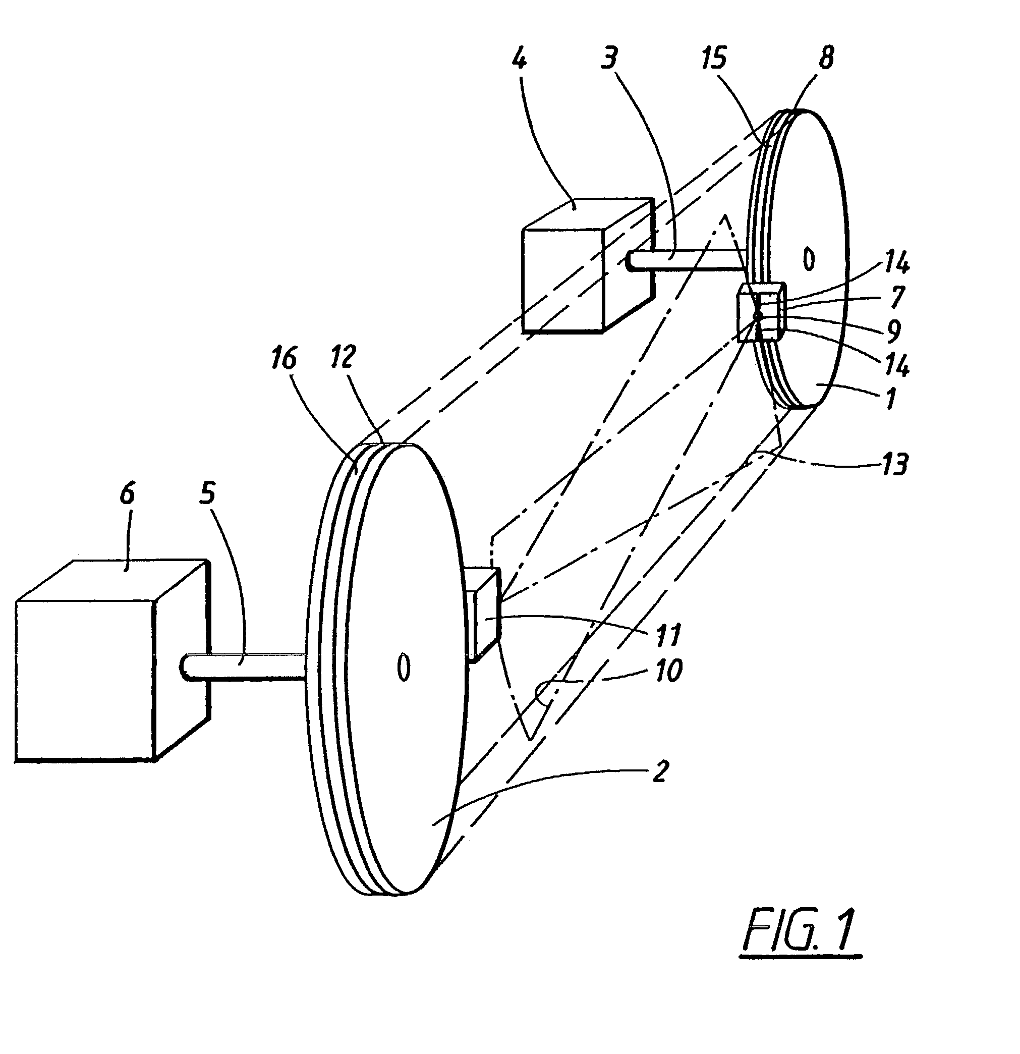
[0025]FIG. 1 shows a perspective view of a device according to the present invention. The invention is particularly, but not exclusively, intended to be used at alignment of two belt pulleys 1, 2 in relation to each other, i.e. position them along an imaginary common plane, whereby twist, angular and parallel errors between the belt pulleys 1, 2 are reduced or preferably eliminated.

[0026]The invention is suitable to be used at the type of alignment of two components in relation to each other where there is a desire to position these two components along a common plane. In particular, the invention may be used at applications which comprise power transfer by means of rotating transmission devices of, for example, the type chain drive or belt drive, and may then be used in connection with, for example, fan systems or machines.

[0027]The invention will in the following be described with reference to an embodiment comprising belt drive, where a power transfer between a first axis and a s...


PUM


Abstract

The invention relates to a device for alignment of a first component (1; 25) and a second component (2; 26) in a predetermined relation to each other, comprising first measuring unit (7; 7′; 7″) arranged to be mounted on said first component (1; 25) and comprising a light-source (9) for generation of light-radiation (10; 10′) with a predetermined pattern in direction towards a second measuring unit (11; 11′) arranged to be mounted on said second component (2; 26) and also comprising a second light-source for generation of light radiation (13; 13′) with a predetermined pattern in direction towards said first measuring unit (7; 7′; 7″), were each of the measuring units (7, 11; 7′; 7″, 11′) comprises a detection device for emitted light radiation. The invention is characterized in that each of the measuring units (7, 11; 7′; 7″, 11′) comprises at least one reference component (18a, 18b, 19a, 19b) which during said alignment is connected with a predetermined position on respective component (1, 2; 26, 26). The invention then provides an improved alignment of for example belt pulleys with consideration to the position of one or more belts for use at the belt pulleys.

Description

[0001]This application is the national phase under 35 U.S.C. § 371 of PCT International Application No. PCT / SE01 / 00020 which has an International filing date of Jan. 5, 2001, which designated the United States of America.[0002]1. Technical Field[0003]The present invention relates to a device for aligning a first component and a second component in a predetermined relation to each other. The device comprises a first measuring unit which is arranged for mounting on said component and which comprises a light source for generation of light radiation with a predetermined pattern in a direction towards a second measuring unit arranged for mounting on said second component. The second measuring unit also comprises a second light source for generation of light radiation with a predetermined pattern in a direction towards said first measuring unit. Each one of the measuring units also comprises a detection device for emitted light radiation.[0004]The invention also related to a procedure for...

Claims


Application Information

Patent Timeline
Patent Type & Authority Patents(United States)
IPC IPC(8): G01B11/27
CPCG01B11/272Y10S33/21
Inventor SEGERSTROM, MARTINJON.ANG.KER, DANIELBODGREN, JAN
Owner A P FIXTURLASER
Why Eureka
Try Eureka