Roller construction module having an error prevention structure

a construction module and error prevention technology, applied in the field of rolling construction modules, can solve problems such as errors

Inactive Publication Date: 2005-11-22
SPEED TECH
View PDF5 Cites 26 Cited by
  • Summary
  • Abstract
  • Description
  • Claims
  • Application Information

AI Technical Summary

Benefits of technology

[0004]The main purpose of the present invention is that, by the first and the second protecting rod, the switch at the left or the right side of the roller construction module is correctly activated and the switch at the middle area under the base is prevented from being activated simultaneously so that error prevention is achieved.
[0005]To achieve the above purpose, the present invention is a roller construction module comprising a base and a roller. Two opposite ends of the base comprise respectively a terminal to be electrically connected with a metal ring inside the roller. A first and a second plungers are at the two ends of a side on the bottom of the base, wherein a post is between the first and the second plunger; and a third plunger is on the corresponding position at the opposite side, wherein a first and a second protecting rods are at two opposite ends near the third plunger. Accordingly, the switch at the left or the right side of the roller construction module can be respectively activated, and another switch, at the middle area under the base, is prevented from being activated simultaneously, so that error prevention is achieved.

Problems solved by technology

Therefore, the roller construction module according to the prior art, if the user continues pressing the same position, another switch, under the bottom surface of the base, will be activated too and an error will occur.

Method used


Image

  • Roller construction module having an error prevention structure
  • Roller construction module having an error prevention structure
  • Roller construction module having an error prevention structure

Examples


Embodiment Construction

[0014]The following descriptions of the preferred embodiment are provided to understand the features and the structures of the present invention.

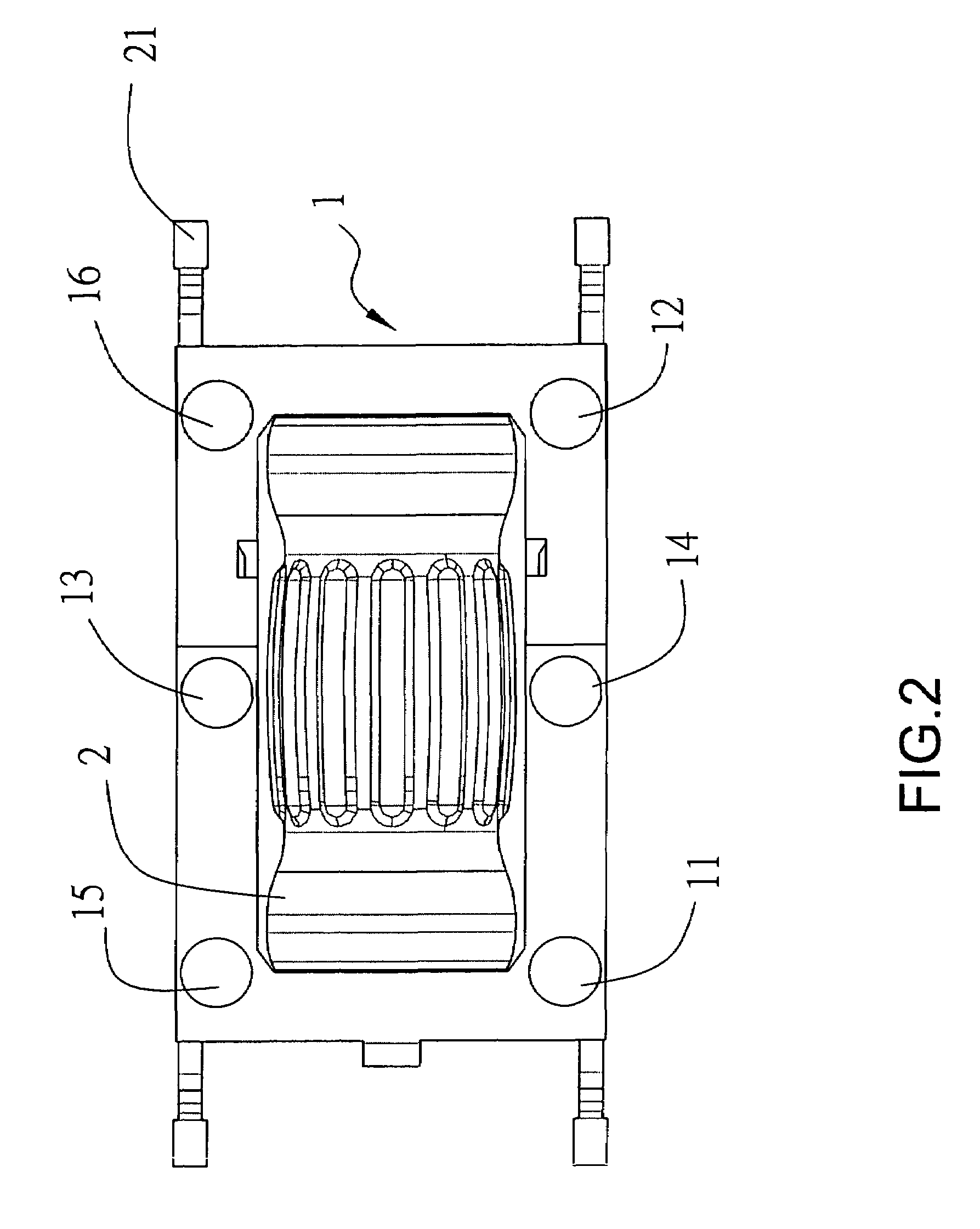
[0015]Please refer to FIG. 1 through FIG. 4, which are views of the preferred embodiment according to the present invention. The present invention comprises an error prevention structure for a roller construction module as a communication interface between a user and an electronic system built in an electronic equipment which can be a PDA, a mobile phone, a Smart Phone, etc. (not shown in the figures). The preferred embodiment is a roller construction module capable of movements along three axes, which are rolling forward and backward, swaying leftward and rightward and moving downward. The preferred embodiment comprises a base 1; a roller 2 disposed in the base 1; two terminals 21 at two opposite ends of the base 1 to be electrically connected with a copper ring inside the roller 2; a first plunger 11 and a second plunger 12 at two opposit...


PUM


Abstract

The present invention is a roller construction module having an error prevention structure, comprising a base; a roller disposed in said base; two terminals at two opposite ends of the base to be electrically connected with a metal ring in the roller; a first and a second plungers on the bottom surface of the base; a post between the first and the second plungers; a third plunger on the position at the opposite side to the post on the bottom surface; and a first and a second protecting rods at two opposite ends near the third plunger. Based on the above-said structure, the switch at the left or the right side of the roller construction module can be respectively activated, and another switch, at the middle area of the mobile device, can be prevented from being activated simultaneously so that error prevention is achieved.

Description

FIELD OF THE INVENTION[0001]The present invention relates to a roller construction module; more particularly, to a roller construction module preventing from simultaneously activating another switch positioned at the area between the left switch and the right switch while correctly activating a switch, either at the left or the right side, so that error prevention is achieved.DESCRIPTION OF THE RELATED ART[0002]The technology of wireless communication has progressed a lot during the past years, so the role of a roller construction module is becoming increasingly important. Traditionally, the prior art of a roller construction module which is capable of movements in three axes (rolling forward and backward, swaying leftward and rightward and moving downward) is shown in FIG. 5 and FIG. 6. The device comprises an insulation bushing 4 outside a copper ring 41 (an encoder and a plunger), wherein the copper ring is a hollow cylinder. Two plastic shafts 51 on the base 5 are plugged into t...

Claims


Application Information

Patent Timeline
Patent Type & Authority Patents(United States)
IPC IPC(8): H01H19/58H01H19/00H01H25/00
CPCH01H25/008G05G9/047H01H2019/146
Inventor CHEN, LI-SENHSU, CHIEN-YULI, CHANG-YI
Owner SPEED TECH
Why Eureka
Try Eureka