Method of obtaining a carbon fiber fabric by continuously carbonizing a cellulose fiber fabric

a technology of cellulose fiber fabric and carbon fiber yarn, which is applied in the chemical characteristics of fibres, textiles and papermaking, weaving, etc., can solve the problem that cellulose fiber yarn is subject to significant shrinkag

Inactive Publication Date: 2005-11-22
GERAKL
View PDF9 Cites 32 Cited by
  • Summary
  • Abstract
  • Description
  • Claims
  • Application Information

AI Technical Summary

Benefits of technology

[0017]An object of the invention is to avoid those drawbacks by proposing a method of obtaining carbon fiber fabrics by carbonizing cellulose fiber fabrics, in which method a carbon fiber fabric is obtained, that does not present significant deformation.
[0022]The selection of this particular temperature profile during carbonization satisfies the concern to find the best compromise between the quality of carbonization, from which in particular the mechanical behavior of the fibers depends, the quality of the appearance of the fabric, i.e. the absence of significant warp shrinkage and an unaltered warp / weft geometrical configuration, and keeping production costs down to an acceptable level.
[0029]The temperature profile also seeks to satisfy a second concern, that of obtaining good mechanical quality for the carbon fibers that result from the carbonization. Thus, in an intermediate stage where most of the cellulose decomposition takes place, temperature rises more slowly so as to comply as well as possible with decomposition kinetics. Selecting a mean temperature rise speed lying in the range 2° C. / min to 10° C. / min makes it possible to satisfy this concern in satisfactory manner without requiring the fabric to follow a path that is of excessive length.
[0030]The final stage of carbonization, which seeks essentially to confer the desired structure on the carbon, can again be performed with a faster rate of temperature rise, since nearly all of the warp and weft shrinkage has already taken place, thereby reducing the total duration of carbonization, and thus reducing production costs.
[0032]According to another feature of the method, the transit time of the fabric through the chamber lies in the range 20 min to 2 hours (h). Carbonization is thus extremely fast.

Problems solved by technology

During carbonization, a cellulose fiber yarn is subject to significant shrinkage.

Method used


Image

  • Method of obtaining a carbon fiber fabric by continuously carbonizing a cellulose fiber fabric
  • Method of obtaining a carbon fiber fabric by continuously carbonizing a cellulose fiber fabric
  • Method of obtaining a carbon fiber fabric by continuously carbonizing a cellulose fiber fabric

Examples


example 1

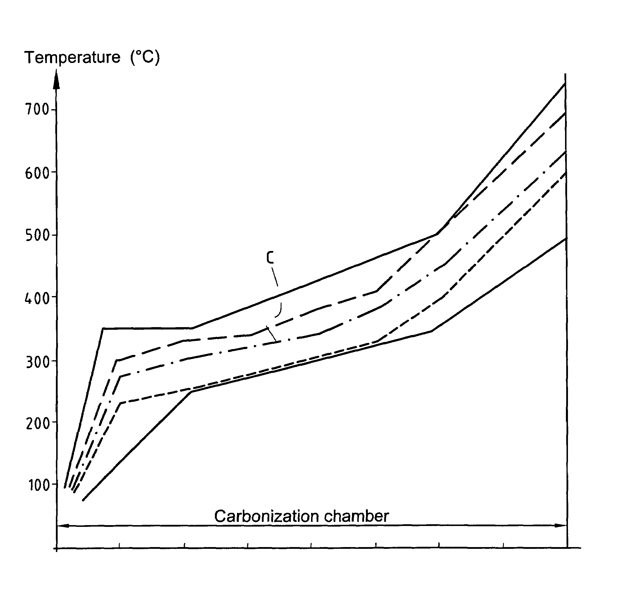
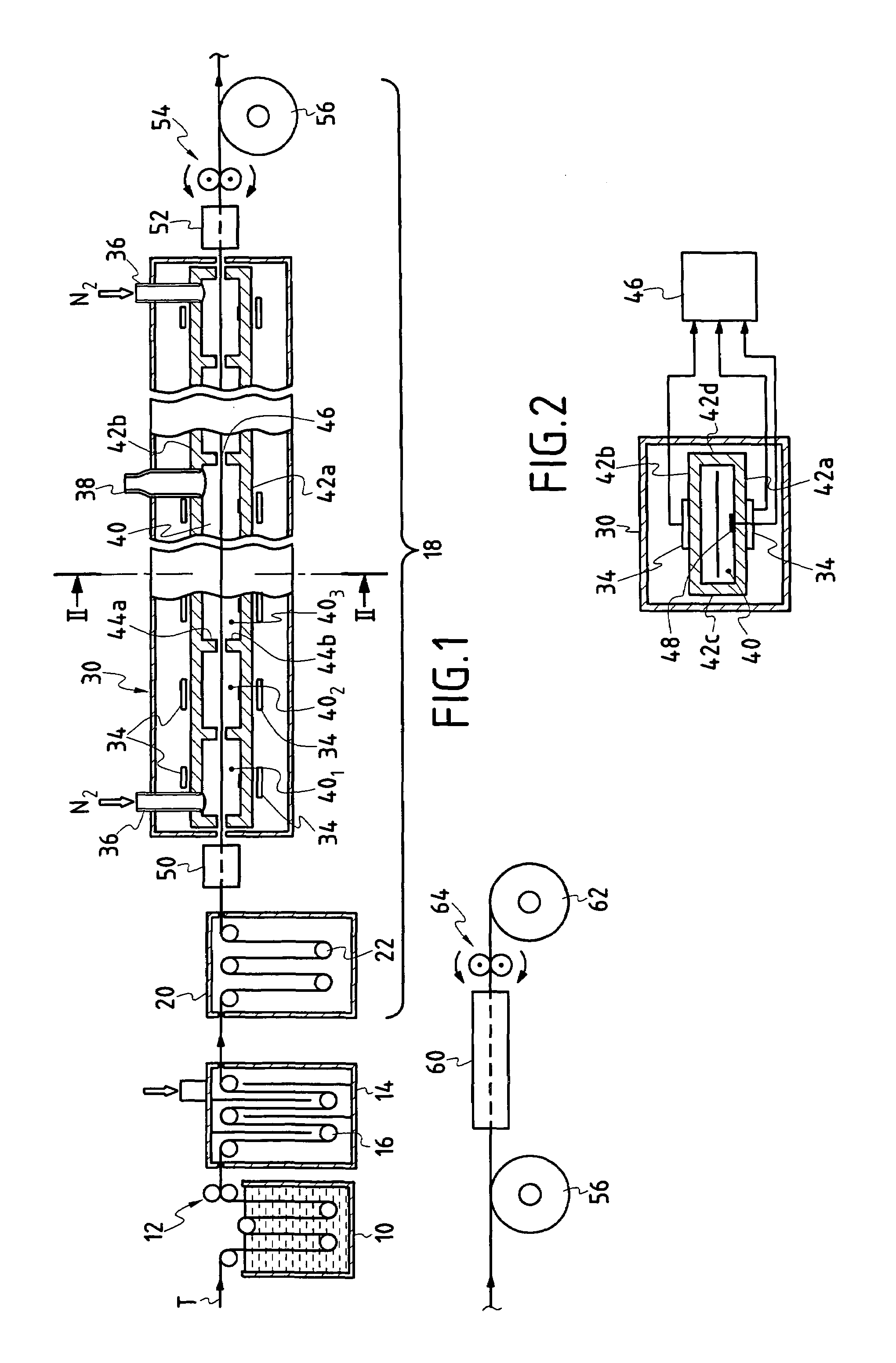
[0082]A carbonization installation was used having a chamber subdivided into eight zones 401 to 408 all of equal length.

[0083]Various strips of the same engineering rayon fabric made using 3600 dtex yarn with warp and weft counts of 11 strands per cm were carbonized in said installation after being subjected to impregnation by an organosilicon compound constituted by a polyhydromethyl-siloxane resin sold by the French company, Rhodia Silicones, under the reference RHODORSIL RTV 141 B, and drying and relaxation treatment at 170° C. for 90 min.

[0084]The various regulated temperatures in the zones of the oven and the various travel speeds were selected so that the temperatures and temperature rise speeds of the fabric in the various zones of the carbonization chamber 40 lay within the range given in the table below. The temperature limits are drawn as dashed-line curves in FIG. 3. The total times required for carbonization lay in the range 30 min to 70 min.

[0085]

Zone4014024034044054064...


PUM


Abstract

The carbonization of cellulose fiber fabric comprises an initial stage of heat treatment up to 250° C. to 350° C., with a relatively high mean temperature rise speed of 10° C. / min to 60° C. / min, an intermediate stage up to 350° C. to 500° C. with a lower mean temperature rise speed of 2° C. / min to 10° C. / min, and a final stage up to 500° C. to 750° C. with a mean temperature rise speed that is again raised to 5° C. / min to 40° C. / min.

Description

FIELD OF THE INVENTION[0001]The invention relates to manufacturing carbon fiber fabrics from fabric made of fibers of a cellulose material that is a precursor of carbon.[0002]More particularly, but not exclusively, the invention relates to manufacturing carbon fiber fabrics by carbonizing a fabric made of viscose fibers, in particular rayon fibers.BACKGROUND OF THE INVENTION[0003]Cellulose-precursor carbon fibers generally present a porous structure made up of highly disorganized turbostratic carbon, said structure also being highly disoriented relative to the axial direction of the fibers and their pore lattices.[0004]Those characteristics confer low thermoconductivity on the carbon fibers, thereby making them particularly suitable for forming thermal protection coatings, such as ablative coatings for combustion chambers and thruster nozzles.[0005]Other applications have been envisaged for cellulose-precursor carbon fiber fabric, in particular for making heating resistors, making b...

Claims


Application Information

Patent Timeline
IPC IPC(8): D01F9/16D01F9/14D03D15/12
CPCD01F9/16
Inventor OLRY, PIERREKAZAKOV, MARKLOISON, SYLVIEMARAKHOVSKAYA, MARINA
Owner GERAKL
Why Eureka
Try Eureka