Method and apparatus for harvesting crops
a harvester and crop technology, applied in the field of harvesting grain and seed crops, can solve the problems of weeds proliferating, the harvester is not very efficient, and the equipment cost is high, so as to reduce the cost of equipment and improve the efficiency
- Summary
- Abstract
- Description
- Claims
- Application Information
AI Technical Summary
Benefits of technology
Problems solved by technology
Method used
Image
Examples
first embodiment
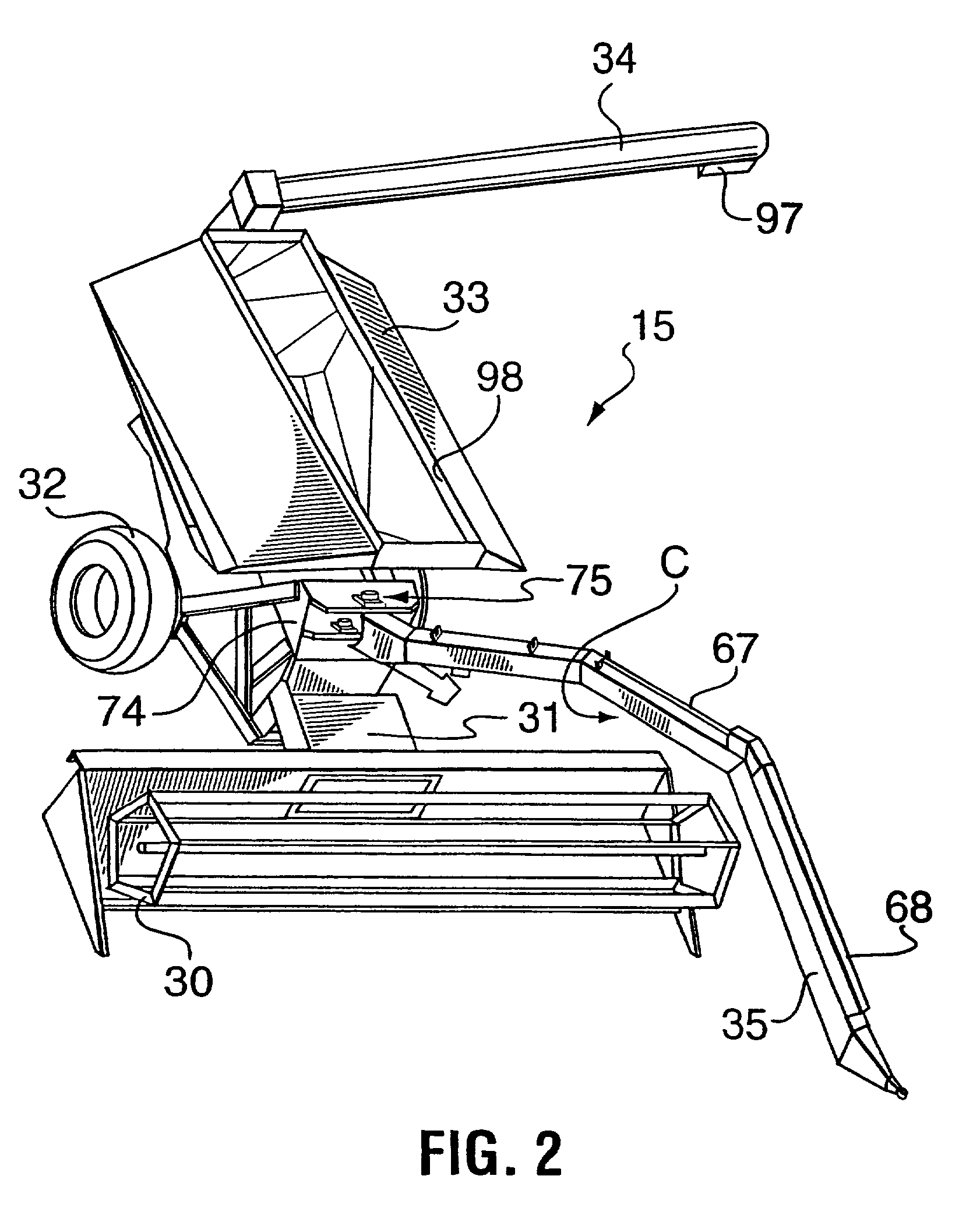
[0089]In a first embodiment, the hitching arm 35 has a closed-in hollow tubular design and, in side view, as best shown in FIG. 3, it has a centrally-raised shape (referred to for convenience in the following as an “inverted U-shape”, although it is realized that this is a very loose description a more accurate description would be that the hitching arm is elongate with two opposite ends; the arm ramps or rises upwardly from each end towards the centre of the arm, and the arm has a short, elevated, generally horizontal section between the ramped or raised sections at in the middle of the arm). The inverted U-shape allows the crook C (upward bend) of the hitching arm to extend over the top of the harvesting header 30, with enough clearance to allow the header to be raised to the elevated (stowed) position shown in FIG. 3. This generally means that the crook C, at its highest point, must be elevated by a distance of at least 3 m (10 feet) from the ground. The length of the hitching ar...
second embodiment
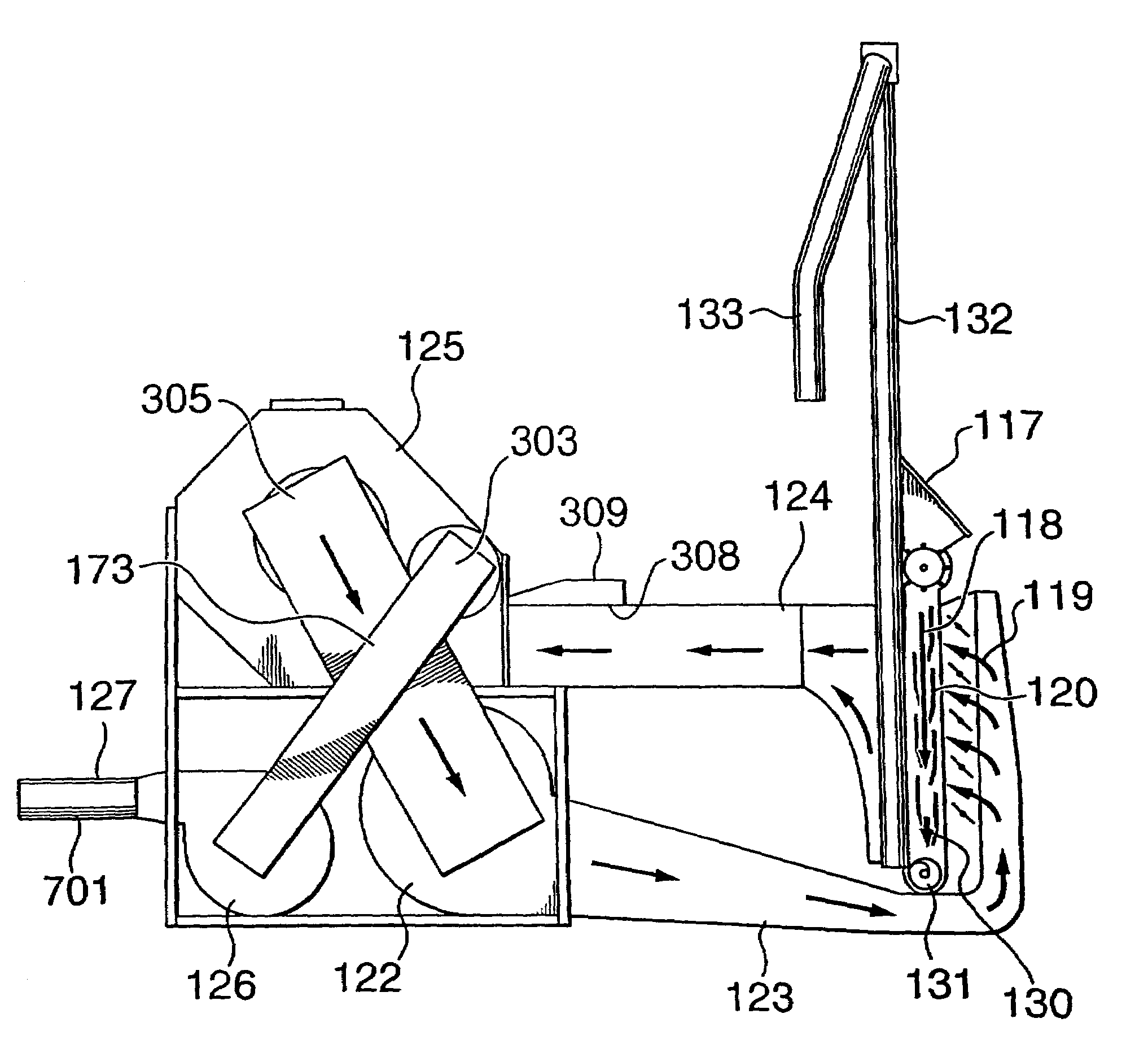
[0116]Firstly, instead of equipping the floor of the tank 33′ with a series of parallel augers, as in the previous embodiment, in order to move the collected graff towards the rear of the tank, a “live floor”810 is provided, i.e. an endless belt made up, for example, of mutually spaced transverse slats driven by chains. This makes use of the principal mentioned earlier that graff may be moved by moving or removing the entire lowermost layer of a body of the graff, i.e. a lowermost layer that extends completely across the width of the body of graff—in this case substantially the entire width of the tank 33′. In the previous embodiment, the intention was to deliver the graff as quickly as possible to a large rear well 96 positioned at the rear of the tank 33 from which the graff can be augered out as shown in FIG. 7D. In this second embodiment, the approach taken to graff removal is different. Instead of the large well 96, the tank 33′ is provided with a shallow transverse well or cha...
PUM
 Abstract
Description
Claims
Application Information
 - R&D Engineer
- R&D Manager
- IP Professional
- Industry Leading Data Capabilities
- Powerful AI technology
- Patent DNA Extraction
Browse by: Latest US Patents, China's latest patents, Technical Efficacy Thesaurus, Application Domain, Technology Topic, Popular Technical Reports.
© 2024 PatSnap. All rights reserved.Legal|Privacy policy|Modern Slavery Act Transparency Statement|Sitemap|About US| Contact US: help@patsnap.com


