Valve structure of hydraulic shock absorber for vehicle

a technology of hydraulic shock absorbers and valves, which is applied in the direction of shock absorbers, mechanical equipment, transportation and packaging, etc., can solve the problems of deteriorating ride quality, poor vehicle body pitching control, and insufficient so as to keep the damping force in the low speed range and the damping force in the middle speed range appropriately high, the effect of comfortable ride quality

Inactive Publication Date: 2005-11-22
SHOWA CORP
View PDF5 Cites 3 Cited by
  • Summary
  • Abstract
  • Description
  • Claims
  • Application Information

AI Technical Summary

Benefits of technology

[0008]The object of the present invention is to keep the damping force in the low speed range low so as to obtain a comfortable ride quality, and to make the damping force in the middle speed range appropriately high so as to improve vehicle body pitching control.

Problems solved by technology

However, the damping force in a middle speed range can not be made appropriately high, and vehicle body pitching control is not good in the middle speed range.
The damping force in the low speed range becomes excessive, thereby deteriorating ride quality.

Method used


Image

  • Valve structure of hydraulic shock absorber for vehicle
  • Valve structure of hydraulic shock absorber for vehicle
  • Valve structure of hydraulic shock absorber for vehicle

Examples


Embodiment Construction

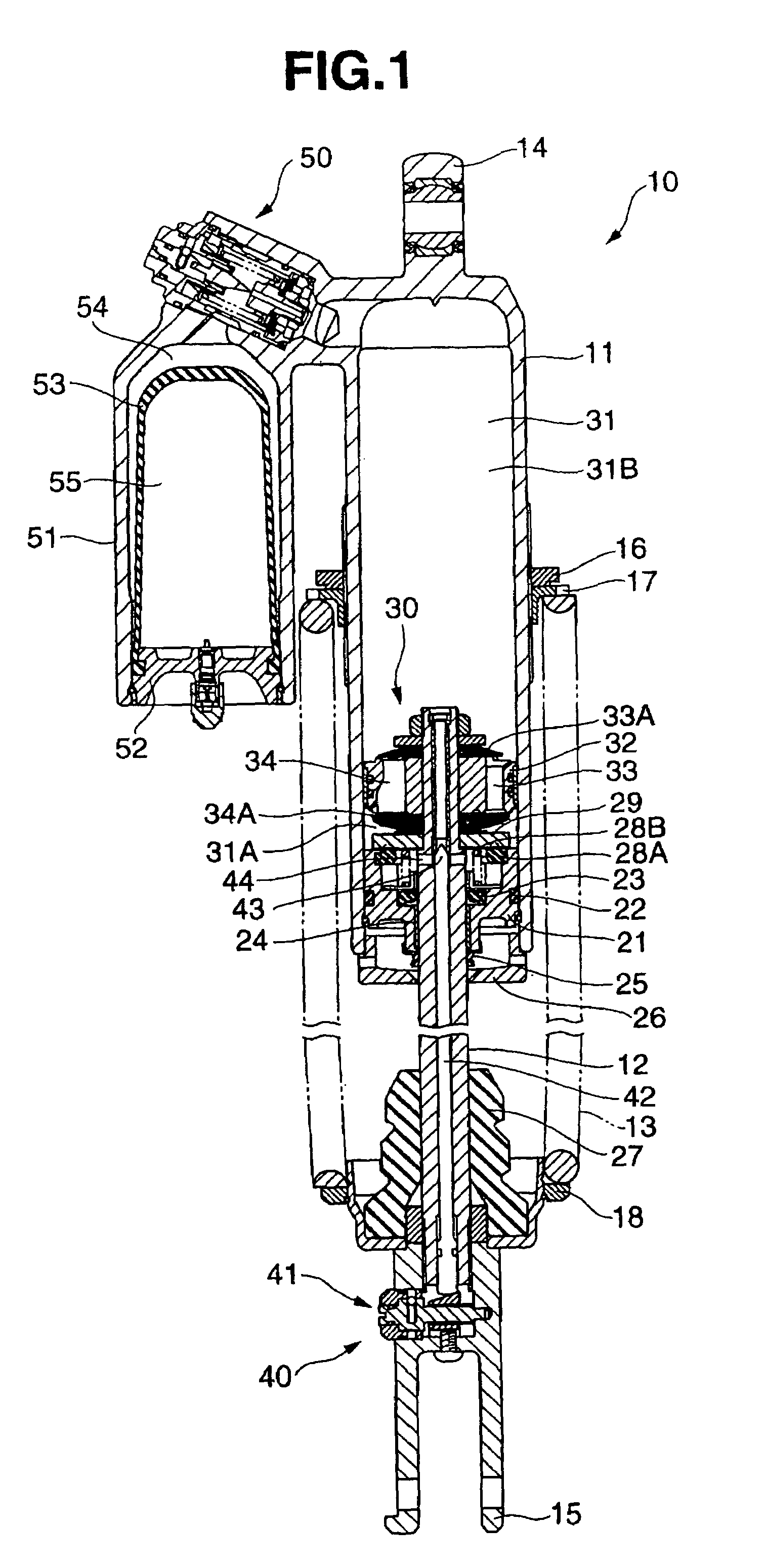
[0017]A hydraulic shock absorber 10 is structured, as shown in FIG. 1, such that a hollow piston rod 12 is inserted into a damper cylinder 11, and a suspension spring 13 is interposed between the damper cylinder 11 and an outer side portion of the piston rod 12.

[0018]The damper cylinder 11 is provided with a vehicle body side mounting portion 14, and the piston rod 12 is provided with an axle side mounting portion 15. A spring receiver adjusting ring 16 and a spring receiver 17 are screwed to an outer peripheral portion of the damper cylinder 11. A spring receiver 18 is fixed to the piston rod 12. The suspension spring 13 is interposed between the spring receiver 17 and the spring receiver 18, and a set length of the suspension spring 13 can be adjusted by a spiral motion of the spring adjusting ring 16 and the spring receiver 17. An elastic force of the suspension spring 13 absorbs impact applied to the vehicle from a road surface.

[0019]The damper cylinder 11 is provided with a rod...


PUM


Abstract

In a valve structure of a hydraulic shock absorber for a vehicle structured by laminating a first leaf valve, a small-diameter leaf valve and a plurality of second leaf valves, an inner leaf valve is provided between a plurality of second leaf valves. An annular outer leaf valve having a larger thickness than that of the inner leaf valve is provided in an outer peripheral side of the inner leaf valve.

Description

BACKGROUND OF THE INVENTION[0001]1. Field of the Invention[0002]The present invention relates to a valve structure of a hydraulic shock absorber for a vehicle.[0003]2. Description of the Related Art[0004]There has been known a hydraulic shock absorber which is interposed between a vehicle body and an axle in a vehicle, and cushions an impact applied to the vehicle from a road surface.[0005]A standard valve apparatus of the conventional hydraulic shock absorber is structured, as shown in FIG. 3B, such that a first leaf valve 2 is provided in an opening portion of a flow passage 1A arranged in a partition wall member 1 constituted by a piston sectioning an oil chamber. A small-diameter leaf valve 3 (an intermediate sheet) is provided on an opposite side of the first leaf valve 2 to a side facing the partition wall member 1. A plurality of second leaf valves 4 are provided in an opposite side of the small-diameter leaf valve 3 to the side facing the first leaf valve 2. The leaf valves ...

Claims


Application Information

Patent Timeline
Patent Type & Authority Patents(United States)
IPC IPC(8): F16F9/34F16F9/348B60G13/08
CPCF16F9/3484
Inventor KAJINO, TSUTOMU
Owner SHOWA CORP
Why Eureka
Try Eureka