Electric generating system for automobiles and its control method

a technology of electric generator and electric motor, which is applied in the direction of electric generator control, engine starter, propulsion by batteries/cells, etc., to achieve the effect of easy mounting

Inactive Publication Date: 2005-11-15
NISSAN MOTOR CO LTD UNDIVIDED 50 INTEREST
View PDF32 Cites 46 Cited by
  • Summary
  • Abstract
  • Description
  • Claims
  • Application Information

AI Technical Summary

Benefits of technology

[0004]It is a main object of the present invention to provide a vehicle driving apparatus capable of being mounted easily even in a narrow space such as an area under the floor. It Is a further typical object of the present invention to provide a vehicle driving apparatus capable of constituting a 4-wheel drive vehicle using an electric motor without using expensive parts such as an inverter.
[0005]The fundamental characteristics of the present invention lies in that a first and a second generators driven by the internal combustion engine for driving one of front and rear wheel of a vehicle are installed in the vicinity of the internal combustion engine in a chamber in which the internal combustion engine is received, a so-called engine room, and an electric motor for driving the other of the front and rear wheels is arranged in the vicinity of a gear mechanism provided on the other axle of the front and rear wheels and with which a reduction mechanism is integrated. With this constitution, even in a narrow space such as a location under the floor of a vehicle, mounting of the vehicle driving apparatus is facilitated.

Problems solved by technology

However, in the former using the electric motor with a reduction gear, since the constitution of the vehicle driving apparatus becomes complicated and becomes large in size, consideration is not taken into the improvement in mounting properties of the vehicle driving apparatus under the floor of the vehicle in a narrow space, and in the latter, since an inverter for driving and controlling the electric motor and an inverter for generating and controlling the electric motor are necessary, consideration is not taken into the enhancement of economization of the vehicle driving apparatus.

Method used


Image

  • Electric generating system for automobiles and its control method
  • Electric generating system for automobiles and its control method
  • Electric generating system for automobiles and its control method

Examples


first embodiment

(First Embodiment)

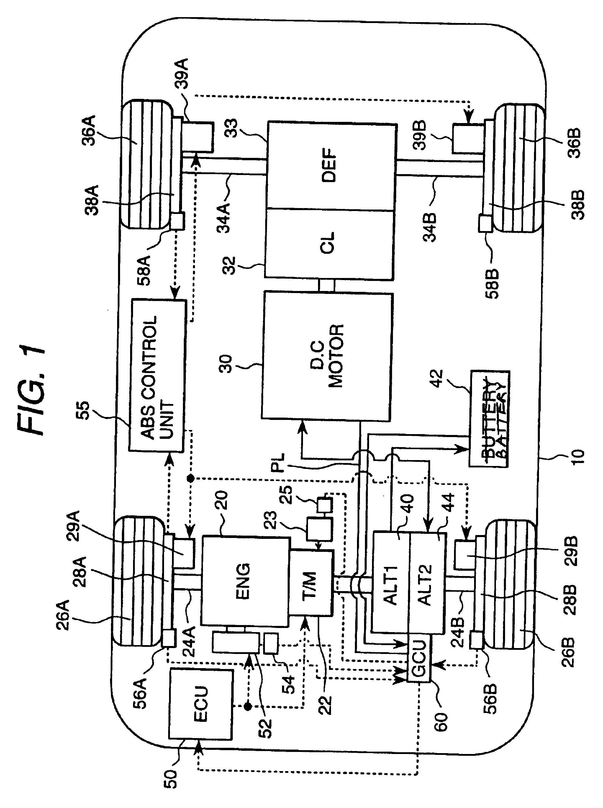
[0027]A first embodiment of the present invention will be described hereinafter with reference to FIGS. 1 to 9. FIG. 1 shows the whole constitution of a 4-wheel drive vehicle. On a 4-wheel drive vehicle 10 are loaded an engine 20 as a driving device and a DC motor 30. The driving force of the engine 20 is transmitted to front wheels 26A and 26B through a transmission 22 and first axles 24A and 24B. Thereby, the font wheels 26A and 26B are driven. The DC motor 30 is connected to rear wheels 36A and 36B through a clutch 32, a differential gear 33 and second axles 34A and 34B. When the DC motor 30 and the differential gear 33 are connected to each other by the clutch 32, the driving force of the DC motor 30 is transmitted to the rear wheels 36A and 36B through the clutch 32, the differential gear 33 and the rear wheels (second axles) 34A and 34B. Thereby, the rear wheels 36A and 36B are driven. When the DC motor 30 and the differential gear 33 are separated from each ...

second embodiment

(Second Embodiment)

[0062]The second embodiment of the present invention will be described below with reference to FIGS. 10 to 14. The present embodiment is an improvement in the first embodiment, in which as the motor for driving the rear wheels, an induction motor is used. In the following description, only part different from the first embodiment will be described. FIG. 10 shows the constitution of part of an electric system of an automobile. Reference numeral 1001 denotes a generator (similar to the second generator 44 in the first embodiment), which comprises a 3-phase armature winding 1011, a field winding 1012 for supplying magnetic flux to the armature winding 1011, and an a current detector 1013. Numeral 1002 denotes an induction motor which comprises an armature winding 1021 for inputting a 3-phase AC current from the armature winding 1011, and a rotation detector 1023. The rotation detector 1023 outputs a pulse according to rotation of the motor 1002. Numeral 1003 denotes ...

third embodiment

(Third Embodiment)

[0094]The third embodiment will be described below with reference to FIG. 15. The present embodiment is a modification of the second embodiment. In the following description, only part different from the second embodiment will be described. FIG. 15 shows the constitution of part of an electric system of an automobile. FIG. 15 corresponds to part of the generator 1001 and the field current control device 1003 in FIG. 10, which comprises N-channel type power MOS 1030a, 1030b, P-channel type power MOS 1030c, 1030d, and diodes 1031a, 1031b, 1031c, 1031d.

[0095]In the FIG. 10 embodiment, the field winding 1012 is energized merely by the power MOS 1030, and a current flows only in one direction, but in the circuit of FIG. 15, when the power MOS 1030c and 1030b are energized, a current flows in a positive direction (the same direction as that of the circuit in FIG. 10), and when the power MOS 1030d and 1030a are energized, a current flows in a reverse direction (opposite ...


PUM


Abstract

The present invention provides a vehicle driving apparatus capable of being mounted easily even in a narrow space such as under-floor of the vehicle. The vehicle driving apparatus comprises a first and a second generators driven by an engine for driving front wheels, and a motor driven by receiving a power supply from the second generator to drive rear wheels, the first and second generators being installed in the vicinity of an engine within an engine room, the motor being arranged in the vicinity of a differential gear with which a reduction mechanism is integrated and is positioned substantially in a central part of the rear wheels.

Description

BACKGROUND OF THE INVENTION[0001]The present invention relates to a vehicle driving apparatus. Conventional vehicle driving apparatuses so far known are described, for example, in Japanese Patent Application Laid-Open Nos. Hei 5-131858 and Hei 11-332019. Out of these two Publications, the former Publication discloses a hybrid vehicle in which front wheels are driven by the engine, and rear wheels are driven by an electric motor with a reduction gear, wherein at the start of the vehicle, a start acceleration according to the road surface condition is obtained, and the motor is controlled so as to able to obtain the start acceleration to enhance the start performance.[0002]The latter Publication discloses a 4-wheel drive vehicle in which a prime mover is connected to a first driving shaft through an electric motor, and an electric motor is provided on a second driving shaft, wherein the electric motor for the first driving shaft is driven by the prime mover to generate electricity, an...

Claims


Application Information

Patent Timeline
Patent Type & Authority Patents(United States)
IPC IPC(8): B60L11/12B60L11/02B60K6/04B60K6/00H02K23/02H02K23/06B60K17/16B60K17/356B60K17/34B60K6/26B60K6/40B60K6/44B60L50/15B60K6/46B60K6/52B60K6/547B60W10/06B60W10/08B60W20/00
CPCB60K6/26B60K6/44B60K6/46B60K6/52B60K6/547B60L11/12B60W10/06B60W10/08B60W20/00H02K23/06B60K6/40Y10S903/919B60K17/16B60K17/356B60L2240/486B60W2710/105Y02T10/6217Y02T10/623Y02T10/6265Y02T10/6286Y02T10/641Y02T10/7077Y10S903/903Y10S903/951Y10S903/906Y10S903/916B60L15/2054B60L2240/423B60L2240/507Y02T10/72B60L50/52Y02T10/62Y02T10/64Y02T10/70B60W20/10
Inventor FUKASAKU, YOSHINORIYAMAMOTO, TATSUYUKIMAEDA, YUUJIMASHINO, KEIICHITAJIMA, SUSUMUSHIMIZU, HISAYANISHIDATE, KEISUKEINNAMI, TOSHIYUKI
Owner NISSAN MOTOR CO LTD UNDIVIDED 50 INTEREST
Why Eureka
Try Eureka