
Normally closed solenoid-operated valve

a solenoid-operated valve, closed technology, applied in valve details, valve arrangements, braking systems, etc., can solve the problems of inability to achieve damping effect, inability to reduce operation noise satisfactorily, delay in operation response of solenoid-operated valve, etc., to prevent operation delay and effectively restrict operation noise

Active Publication Date: 2005-11-01
ADVICS CO LTD
View PDF8 Cites 22 Cited by
  • Summary
  • Abstract
  • Description
  • Claims
  • Application Information

AI Technical Summary

Benefits of technology

The present invention provides an improved solenoid-operated valve that is inexpensive and can effectively restrain the operation noise and prevent delay in response. The valve has a normally closed state and an open state. When the valve is in the open state, a damper chamber is created between the stationary and movable elements, and the operating fluid flows through a communication groove and a fixed throttle to decrease the throttle resistance and slow down the movement of the movable element, thus reducing the operation noise. When the valve is in the closed state, the damper chamber is closed, and the operating fluid can flow freely through the clearance without being throttled, allowing the movable element to move with high responsiveness. Overall, this valve provides a cost-effective solution for reducing noise and improving response time.

Problems solved by technology

As a result, a delay takes place in the operation response of the solenoid-operated valve.
On the contrary, if preference is taken to the operation responsiveness of the solenoid-operated valve, a problem would arise in that a sufficient damping effect cannot be obtained so that the operation noise cannot be diminished satisfactorily.
Further, the use of the sealing member raises another problem in respect of increasing the manufacturing cost.

Method used


Image

  • Normally closed solenoid-operated valve
  • Normally closed solenoid-operated valve
  • Normally closed solenoid-operated valve

Examples


first embodiment

(First Embodiment)

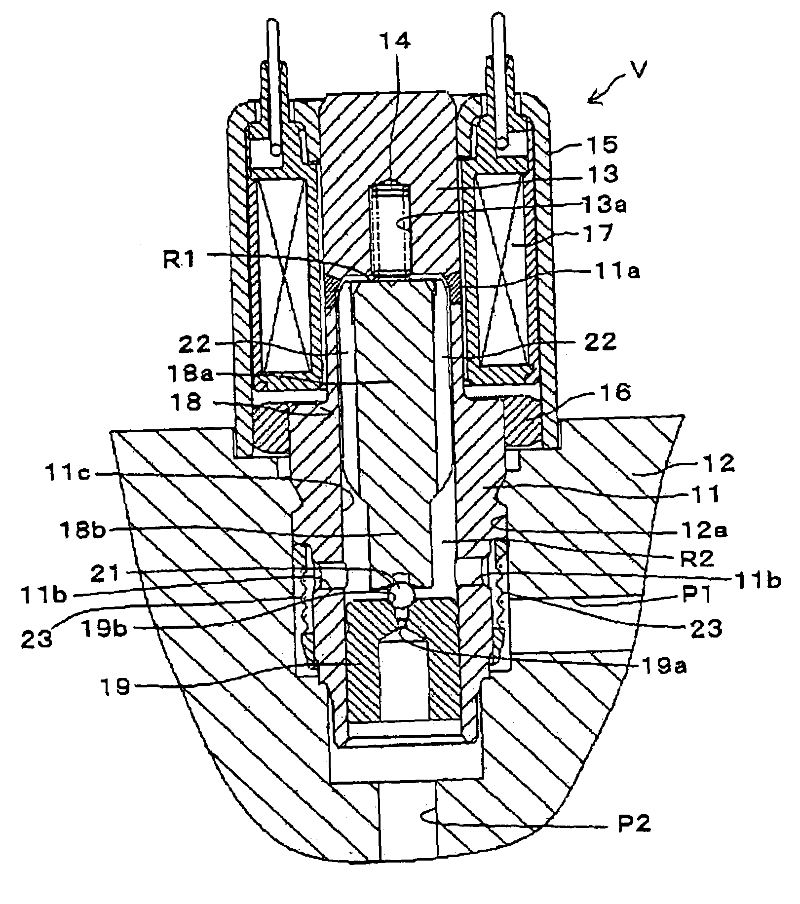
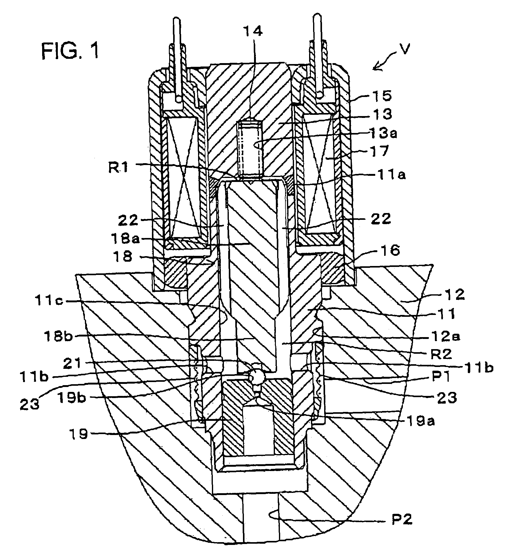
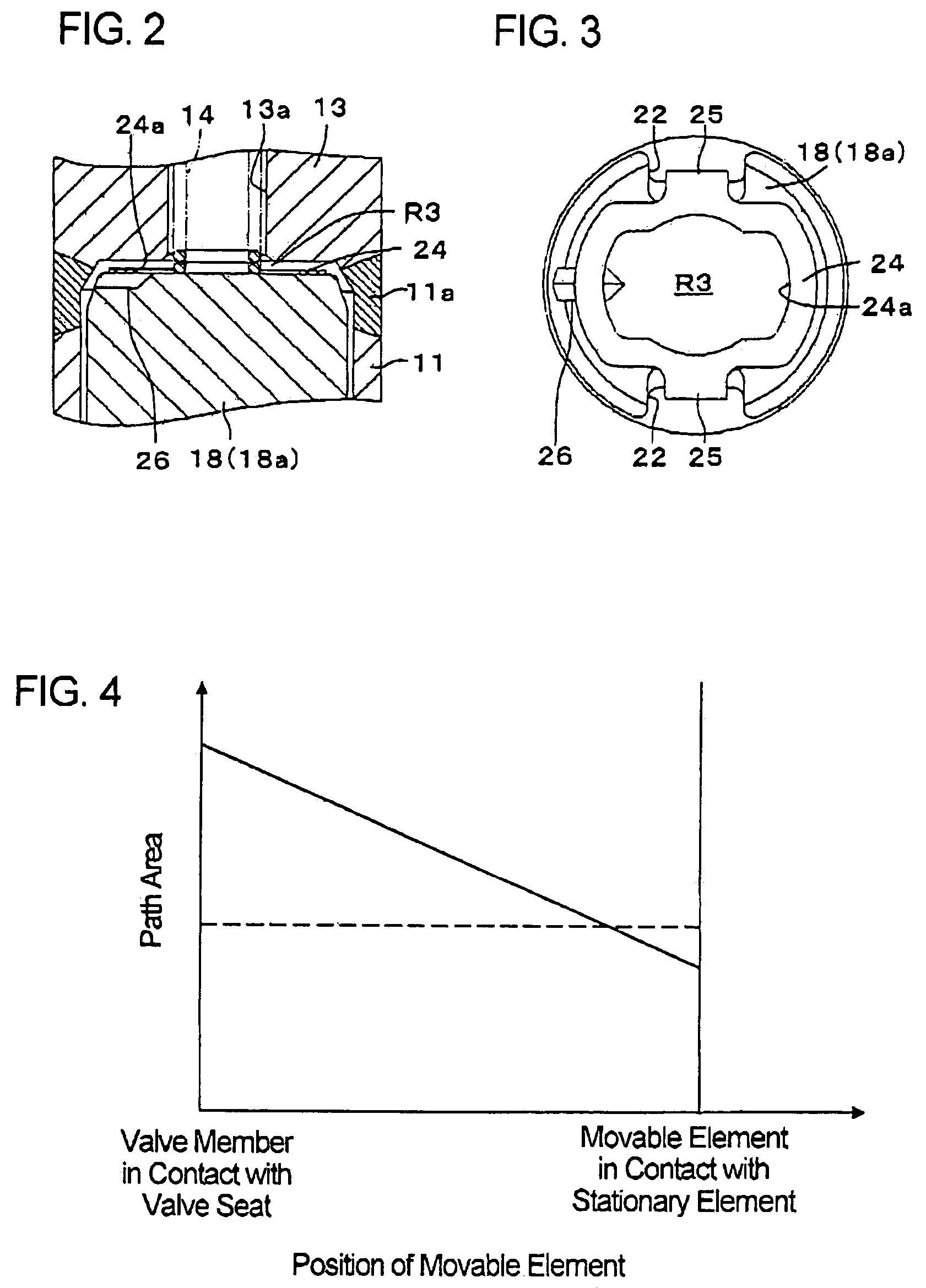
[0020]Hereinafter, a normally closed solenoid-operated valve in the first embodiment according to the present invention will be described with reference to FIGS. 1 to 4. FIG. 1 is a longitudinal section showing the normally closed solenoid-operated valve.

[0021]As shown in FIG. 1, the solenoid-operated valve V of an open / close type is provided with a sleeve 11 formed cylindrically. The lower end portion of the sleeve 11 is inserted into an installation hole 12a provided in a valve body 12 and is fluid-tightly secured thereto by caulking. The upper portion of the sleeve 11 is protruded from the valve body 12 and is provided at its upper end portion with a stationary element 13 of a cylindrical shape. The stationary element 13 is provided coaxially and bodily with the sleeve 11 and has the same diameter as the upper portion of the sleeve 11. A non-magnetic material 11a is interposed at the boundary portion between the stationary element 13 and the sleeve 11. An axial ...


PUM


Abstract

A normally closed solenoid-operated valve is composed of a stationary element provided at one end of a stationary sleeve, a movable element slidably inserted in the sleeve to face the stationary element and provided at an external surface thereof with a communication groove which axially extends between the opposite ends thereof for permitting the flow of the operating fluid, and an electromagnetic coil for exciting the stationary element and the movable element. A damper chamber is defined by an annular shim provided between the lower end surface of the stationary element and the top surface of the movable element. When the damper chamber is closed by the lower end surface of the stationary element and the top surface of the movable element, a dent groove makes the damper chamber communicate with the communication groove.

Description

INCORPORATION BY REFERENCE[0001]This application is based on and claims priority under 35 U.S.C. sctn. 119 with respect to Japanese Application No. 2002-347509 filed on Nov. 29, 2002, the entire content of which is incorporated herein by reference.BACKGROUND OF THE INVENTION[0002]1. Field of the Invention[0003]The present invention relates to a normally closed solenoid-operated valve for controlling the flow of fluid such as hydraulic oil or the like in response to an electric command applied to an electromagnetic coil which excites the solenoid-operated valve.[0004]2. Discussion of the Related Art[0005]Heretofore, as normally closed solenoid-operated valves of this type, there has been known one described in the U.S. Pat. No. 5,601,275 to the inventor of the present application. The known valve is provided with a cylindrical sleeve, a stationary element provided at one end of the cylindrical sleeve, a movable element inserted slidably within the sleeve to move relative to the stati...

Claims


Application Information

Patent Timeline
Patent Type & Authority Patents(United States)
IPC IPC(8): F16K31/06B60T8/36
CPCB60T8/363F16K31/0665
Inventor HIRONAKA, HIDEHARU
Owner ADVICS CO LTD
Learn More