Ultrasound analysis of slurries

a technology of ultrasonic transducers and slurries, which is applied in the direction of analysing fluids using sonic/ultrasonic/infrasonic waves, instruments, and specific gravity measurements, etc. it can solve the problems of inability to operate in inability to use high temperature and high pressure environments, and inability to use ultrasonic transducers under ambient conditions

Inactive Publication Date: 2005-11-01
THE UNITED STATES AS REPRESENTED BY THE DEPARTMENT OF ENERGY
View PDF9 Cites 20 Cited by
  • Summary
  • Abstract
  • Description
  • Claims
  • Application Information

AI Technical Summary

Benefits of technology

[0013]The present invention contemplates the use of measurements in changes of velocity (transit time) and attenuation (amplitude ratio) of sound waves traveling through a sample under investigation such as a slurry. Changes in transit time and amplitude ratio are used to determine slurry concentration and/or particle size distribution, where the slurry may be in gas and/or solid phase. The present invention allows environmentally sensitive transducers to be used with slurries maintained at temperatures above 60° C. and pressures greater than one (1) atmosphere. The transit time and amplitude ratio of the sound wave exhibits a maximum (transit time) and a minimum (amplitude ratio) relationship with the concentration of the slurry. This measurement capability

Problems solved by technology

The primary limitation of this ultrasonic measurement technique has been in its use of its ultrasonic transducers which cannot operate in high temperature and high pressure environments.
This technique can only be used under ambient condi

Method used


Image

  • Ultrasound analysis of slurries
  • Ultrasound analysis of slurries
  • Ultrasound analysis of slurries

Examples


Embodiment Construction

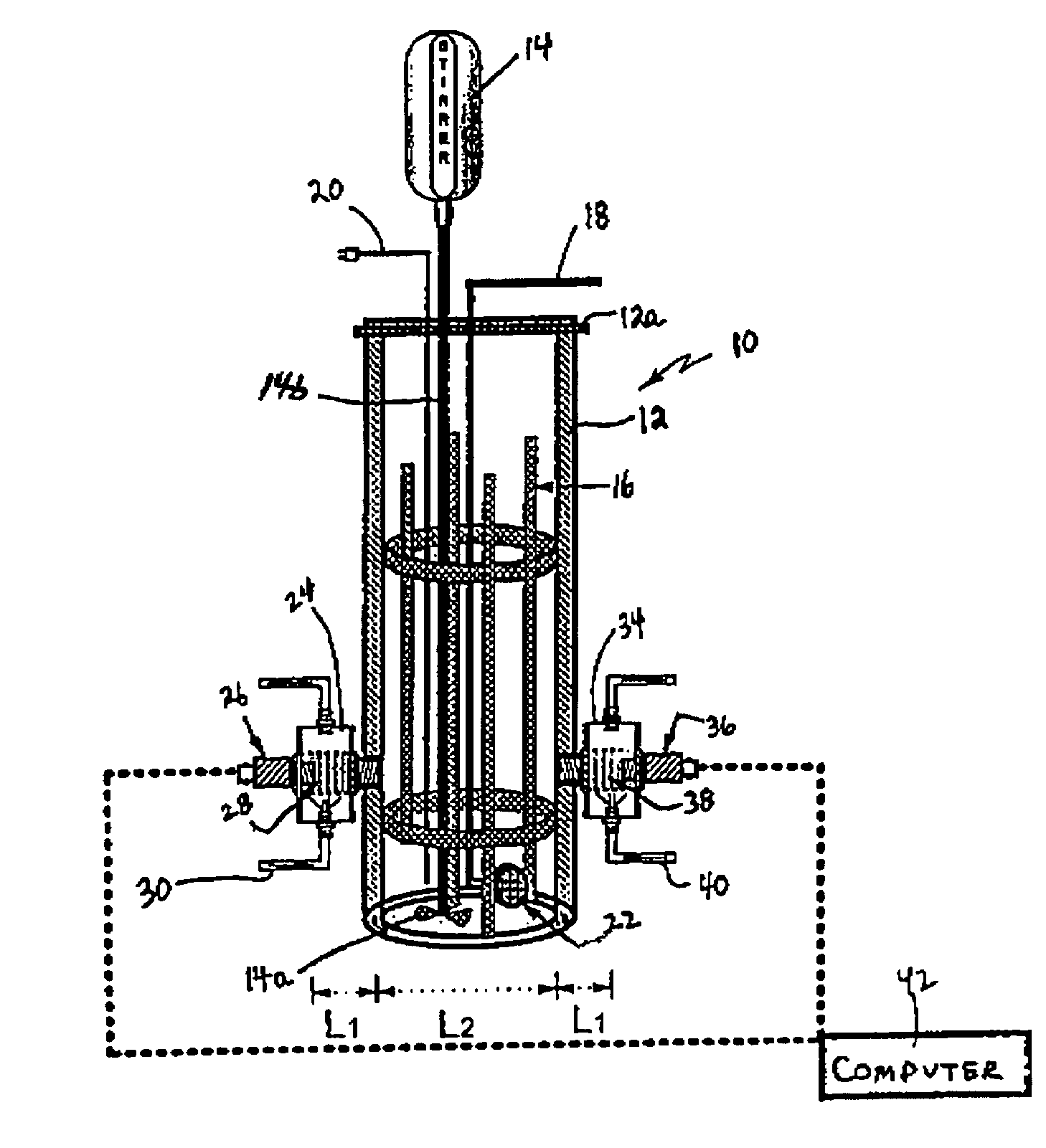
[0041]Referring to FIG. 1, there is shown a schematic diagram of an arrangement for conducting ultrasound analysis of slurries in accordance with the principles of the present invention. The ultrasound analysis arrangement shown in FIG. 1 is particularly adapted for ultrasound analysis of slurries at high temperature. The ultrasound analysis arrangement includes an autoclave reactor 10 comprised of a reactor vessel 12 having a hollowed-out, generally cylindrical shape and including a cover 12a attached to the cylindrical reactor vessel in a sealed manner. Reactor vessel 12 is preferably comprised of stainless steel and in the embodiment shown in FIG. 1 is 10.6 cm. in diameter, 30 cm. in height and has a volume of 2.5 liters. Disposed within the reactor vessel 12 is the slurry being investigated. Also disposed within the reactor vessel 12 are four equally spaced, vertically baffles 16, each 1 / 8 of the diameter of the reactor vessel in width. Extending into the reactor vessel 12 is a ...


PUM


Abstract

An autoclave reactor allows for the ultrasonic analysis of slurry concentration and particle size distribution at elevated temperatures and pressures while maintaining the temperature- and pressure-sensitive ultrasonic transducers under ambient conditions. The reactor vessel is a hollow stainless steel cylinder containing the slurry which includes a stirrer and a N2 gas source for directing gas bubbles through the slurry. Input and output transducers are connected to opposed lateral portions of the hollow cylinder for respectively directing sound waves through the slurry and receiving these sound waves after transmission through the slurry, where changes in sound wave velocity and amplitude can be used to measure slurry parameters. Ultrasonic adapters connect the transducers to the reactor vessel in a sealed manner and isolate the transducers from the hostile conditions within the vessel without ultrasonic signal distortion or losses.

Description

CONTRACTUAL ORIGIN OF THE INVENTION[0001]The United States Government has rights in this invention pursuant to Contract No. W-31-109-ENG-38 between the U.S. Department of Energy and the University of Chicago.FIELD OF THE INVENTION[0002]This invention relates generally to apparatus for analyzing materials in slurry form and is particularly directed to an autoclave arrangement for determining the concentration and / or particle size distribution of a slurry under elevated temperature and pressure conditions.BACKGROUND OF THE INVENTION[0003]Ultrasonic measurement is an established technique for many industrial applications, such as in medical imaging, materials testing, flow detection and level measurements. The ultrasonic technique has advantages over many existing methods because it is a noninvasive and nondestructive measurement of systems which are concentrated, optically opaque and electrically nonconducting. The primary limitation of this ultrasonic measurement technique has been i...

Claims


Application Information

Patent Timeline
IPC IPC(8): G01N29/02G01N15/06G01N29/24G01N29/024G01N29/032G01N29/22
CPCG01N15/06G01N29/024G01N29/032G01N29/222G01N2291/02416G01N2291/02809G01N2291/02836G01N2291/02872G01N2291/02881G01N2291/048G01N2291/102
Inventor SOONG, YEEBLACKWELL, ARTHUR G.
Owner THE UNITED STATES AS REPRESENTED BY THE DEPARTMENT OF ENERGY
Why Eureka
Try Eureka