
Conductive terminal and electrical connector applying the conductive terminal

a technology of conductive terminals and electrical connectors, applied in the direction of coupling contact members, electrical apparatus construction details, coupling device connections, etc., can solve the problems of unsatisfactory signal transmission stability of the above-mentioned structure and electrical connectors, and achieve the effect of enhancing signal transmission reliability and effective reducing inductance values

Active Publication Date: 2005-10-25
MOLEX INC
View PDF6 Cites 28 Cited by
  • Summary
  • Abstract
  • Description
  • Claims
  • Application Information

AI Technical Summary

Benefits of technology

This patent is about a conductive terminal for an LGA (Land Grid Array) that improves electrical connection stability and reduces signal transmission loss. The conductive terminal has a base that is positioned in an insulative housing with receiving cavities and has two resilient arms that form contact portions to connect to an electronic component and a circuit board. The conductive terminal can have a single or dual conducting path to enhance signal transmission reliability. The technical effects of this patent are improved electrical connection stability and reduced signal transmission loss.

Problems solved by technology

However, there are drawbacks with the aforesaid electrical connector.
Therefore, the aforesaid structure is quite unsatisfactory in terms of signal transmission stability.

Method used


Image

  • Conductive terminal and electrical connector applying the conductive terminal
  • Conductive terminal and electrical connector applying the conductive terminal
  • Conductive terminal and electrical connector applying the conductive terminal

Examples


Embodiment Construction

[0022]While the invention may be susceptible to embodiment in different forms, there is shown in the drawings, and herein will be described in detail, a specific embodiment with the understanding that the present disclosure is to be considered an exemplification of the principles of the invention, and is not intended to limit the invention to that as illustrated and described herein.

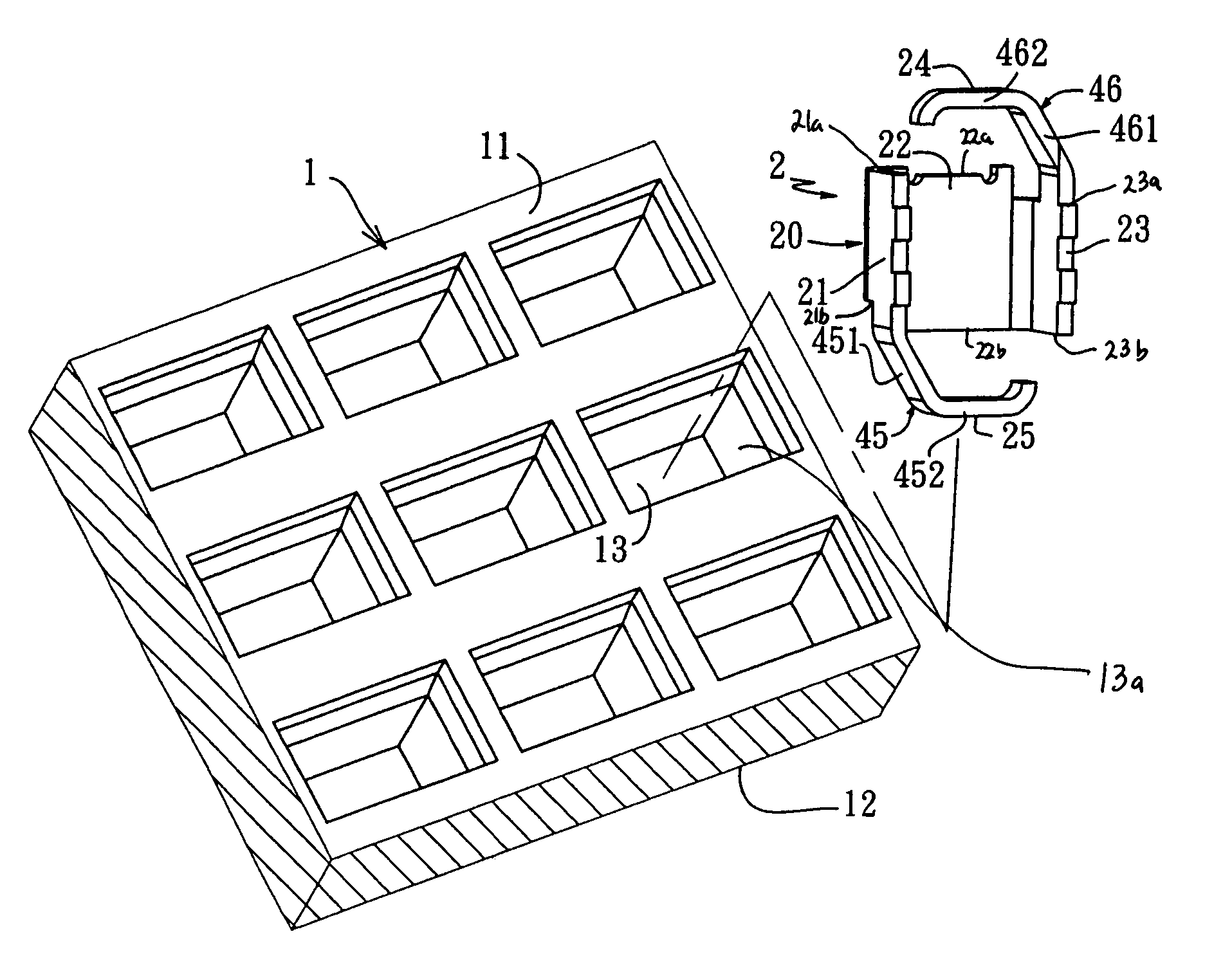
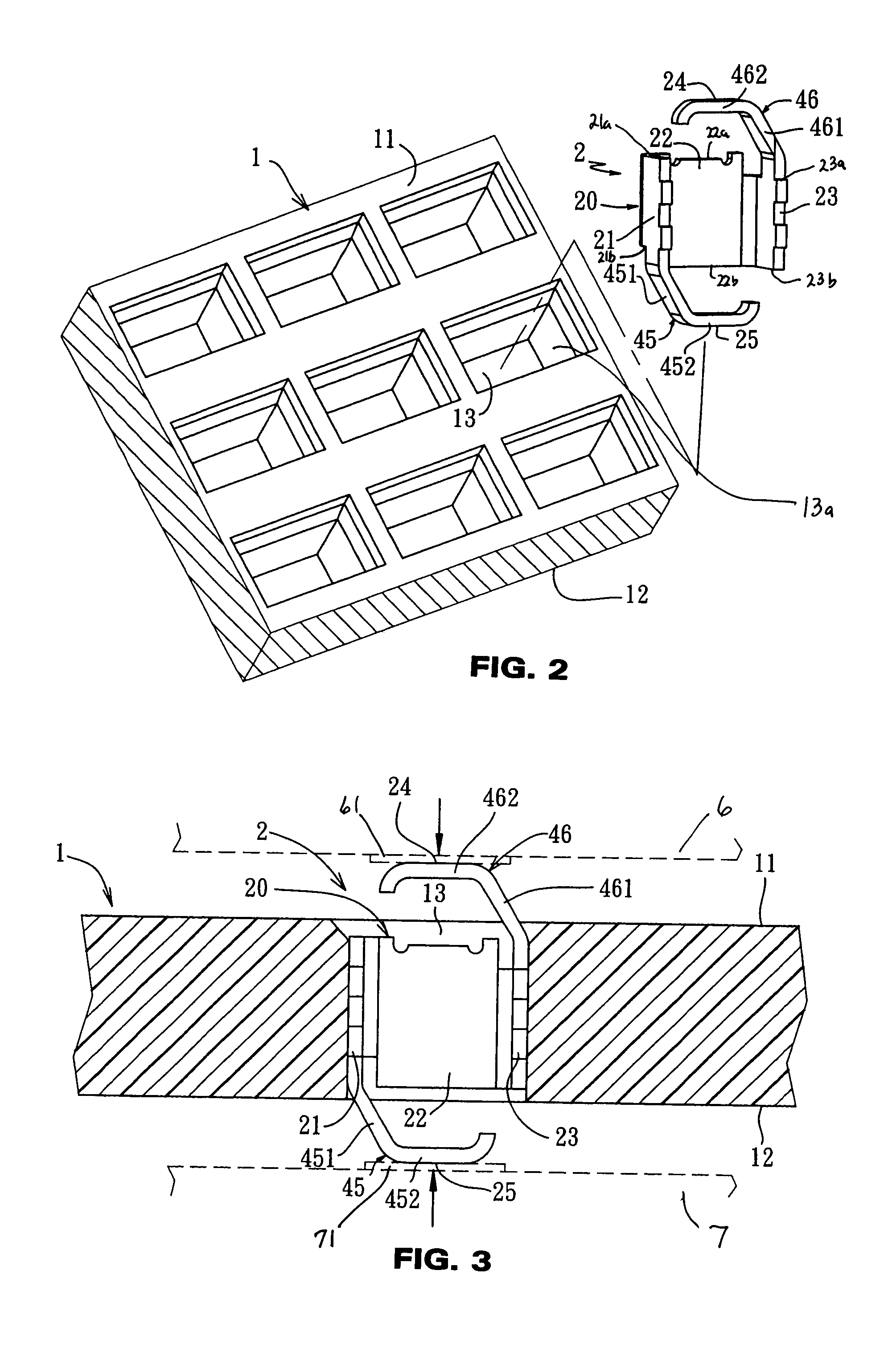
[0023]Referring to FIGS. 2 and 3, similar to the aforesaid conventional structure, the first illustrated embodiment of a conductive terminal and an electrical connector applying the conductive terminal according to this invention is used to connect an electronic component of an integrated circuit of a central processing unit (CPU) with a circuit board. A bottom side of the electronic component 6 has a plurality of contact pads 61 arranged thereon in an array, whereas a surface of the circuit board 7 is provided with a plurality of conductive contact pads 71 at positions corresponding to the contact pads ...


PUM


Abstract

A conductive terminal is positioned in an insulative housing to constitute an electrical connector. The insulative housing is formed with a first face and a second face opposite to each other, and has a plurality of terminal receiving cavities extending through the first face and the second face. The conductive terminal includes a base for abutting against the corresponding terminal receiving cavity to achieve positioning. The base has two spaced-apart opposite sidewalls. Each sidewall is formed with a first edge and a second edge opposite to each other in a direction of extension of the terminal receiving cavity. A plurality of resilient arms extend outwardly from certain of the edges of the sidewalls such that the first and second contact portions of the resilient arms are respectively and electrically connected to an electronic component and a circuit board to transmit signals between the electronic component and the circuit board through the conductive terminal.

Description

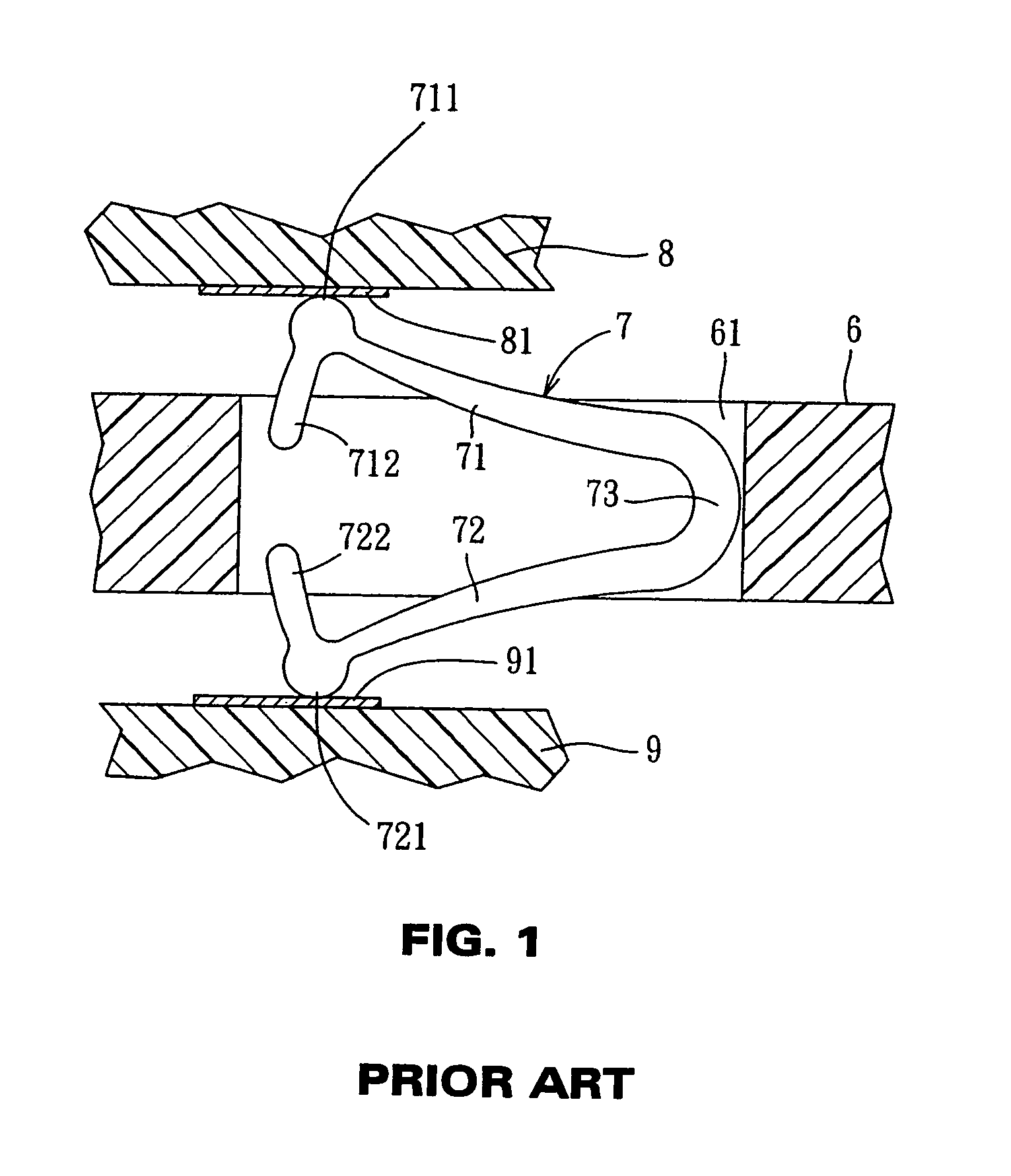
FIELD OF THE INVENTION[0001]This invention relates to a conductive terminal and an electrical connector using such conductive terminals, and, more particularly, to a conductive terminal applied to an LGA (land grid array) electrical connector.BACKGROUND OF THE INVENTION[0002]Referring to FIG. 1, U.S. Pat. No. 5,653,598 discloses an LGA (land grid array) electrical connector and a conductive terminal employed thereby, in which a tightening member (not shown) is generally used to clamp the electrical connector between a packaged integrated circuit (IC) 8 and a circuit board 9 so as to establish electrical connection without the need for a soldering step.[0003]A bottom side of the integrated circuit 8 is formed with conductive contact pads 81 that are arranged in an array, and the circuit board 9 also has conductive contact pads 91 provided thereon at positions corresponding to the contact pads 81 of the integrated circuit 8. The integrated circuit 8 and the circuit board 9 are respect...

Claims


Application Information

Patent Timeline
Patent Type & Authority Patents(United States)
IPC IPC(8): H01R13/24H01R13/22H01R13/41H01R13/40
CPCH01R13/2435H05K7/10H05K7/1069H01R12/7076H01R12/714
Inventor CHIANG, CHUN-HSIANG
Owner MOLEX INC
Learn More