
Adapter for portable electronic instrument and transmission system between these two elements

a technology for electronic instruments and adapters, which is applied in the direction of coupling device connections, instruments, horology, etc., can solve the problems of additional sealing problems in the case, complex and expensive actuation of said mobile elements, and expensive manufacturing constraints of instruments, so as to achieve simple and inexpensive adaptor construction and simple electric connection

Active Publication Date: 2005-10-18
THE SWATCH GRP RES & DEVELONMENT LTD
View PDF12 Cites 10 Cited by
  • Summary
  • Abstract
  • Description
  • Claims
  • Application Information

AI Technical Summary

Benefits of technology

The present invention proposes a system for transmitting electric signals between a portable electronic instrument and an adaptor. The system includes a portable instrument with conventional control members and an adaptor with a pattern cavity that can receive the control members of the instrument. The control members are pushed into position to create a simple and inexpensive electric connection between the instrument and the adaptor. The pattern cavity has a guide surface, a support surface, and electric contact means for contacting the control members. The technical effect of the invention is to provide a simple and efficient way to transmit electric signals between the portable instrument and an adaptor.

Problems solved by technology

However, such a communication interface has certain drawbacks.
Thus, the use of a manually actuated mobile element requires, on the one hand, means for actuating said mobile element which prove complex and expensive and, on the other hand, particular care by the user to ensure the electric connection between the communication interface and the portable instrument is properly established.
It will also be noted that since the connection elements are carried by the mobile element, the connection terminals have to be arranged in the same zone, which causes expensive manufacturing constraints for the instrument.
Moreover, as mentioned hereinbefore, the connection terminals used are specifically provided for communications between the portable instrument and the interface, which imposes, on the one hand, constraints as regards the arrangement of the conventional control members, and which raises, on the other hand, additional problems of sealing as regards the case of the portable instrument.

Method used


Image

  • Adapter for portable electronic instrument and transmission system between these two elements
  • Adapter for portable electronic instrument and transmission system between these two elements
  • Adapter for portable electronic instrument and transmission system between these two elements

Examples


first embodiment

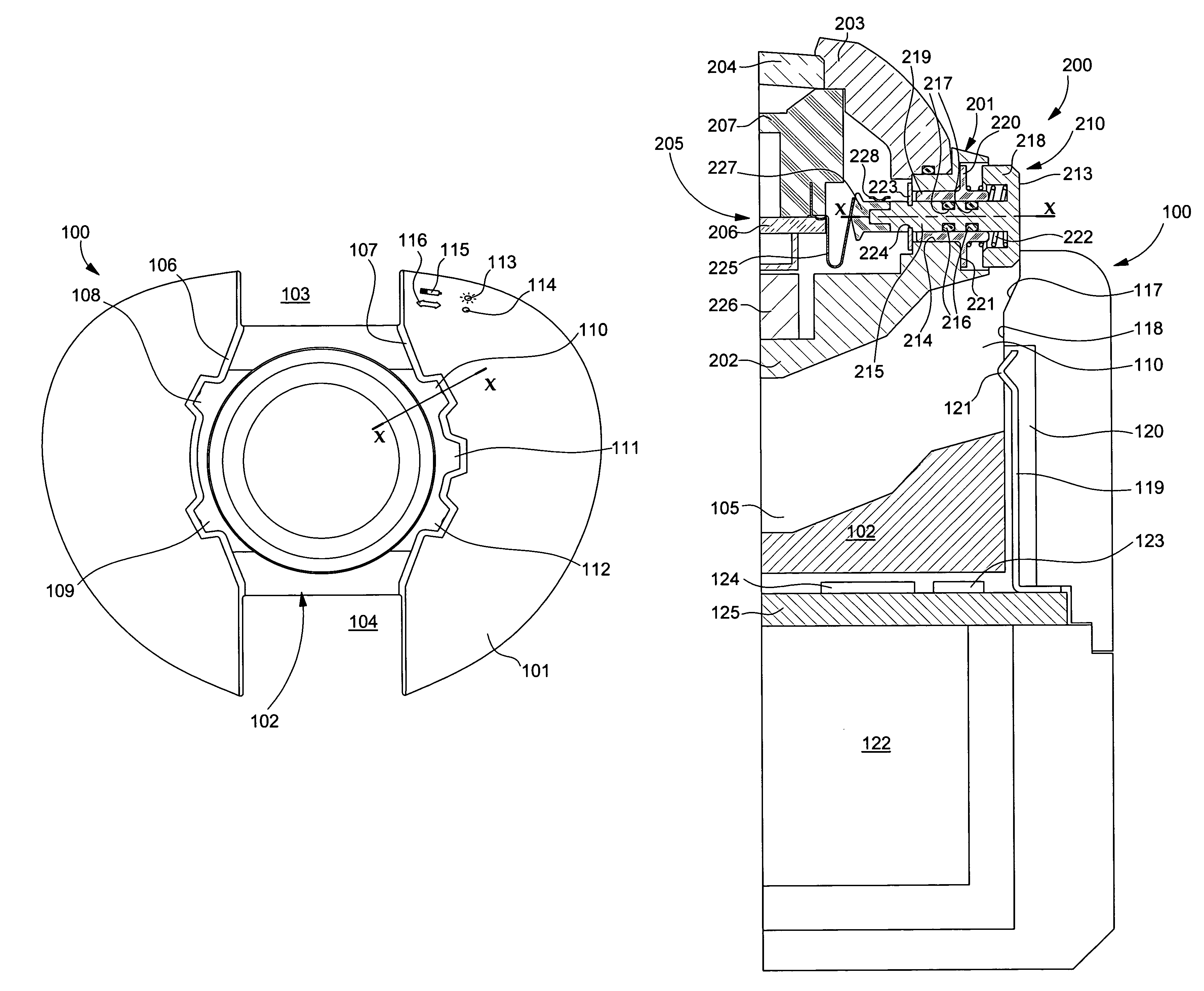
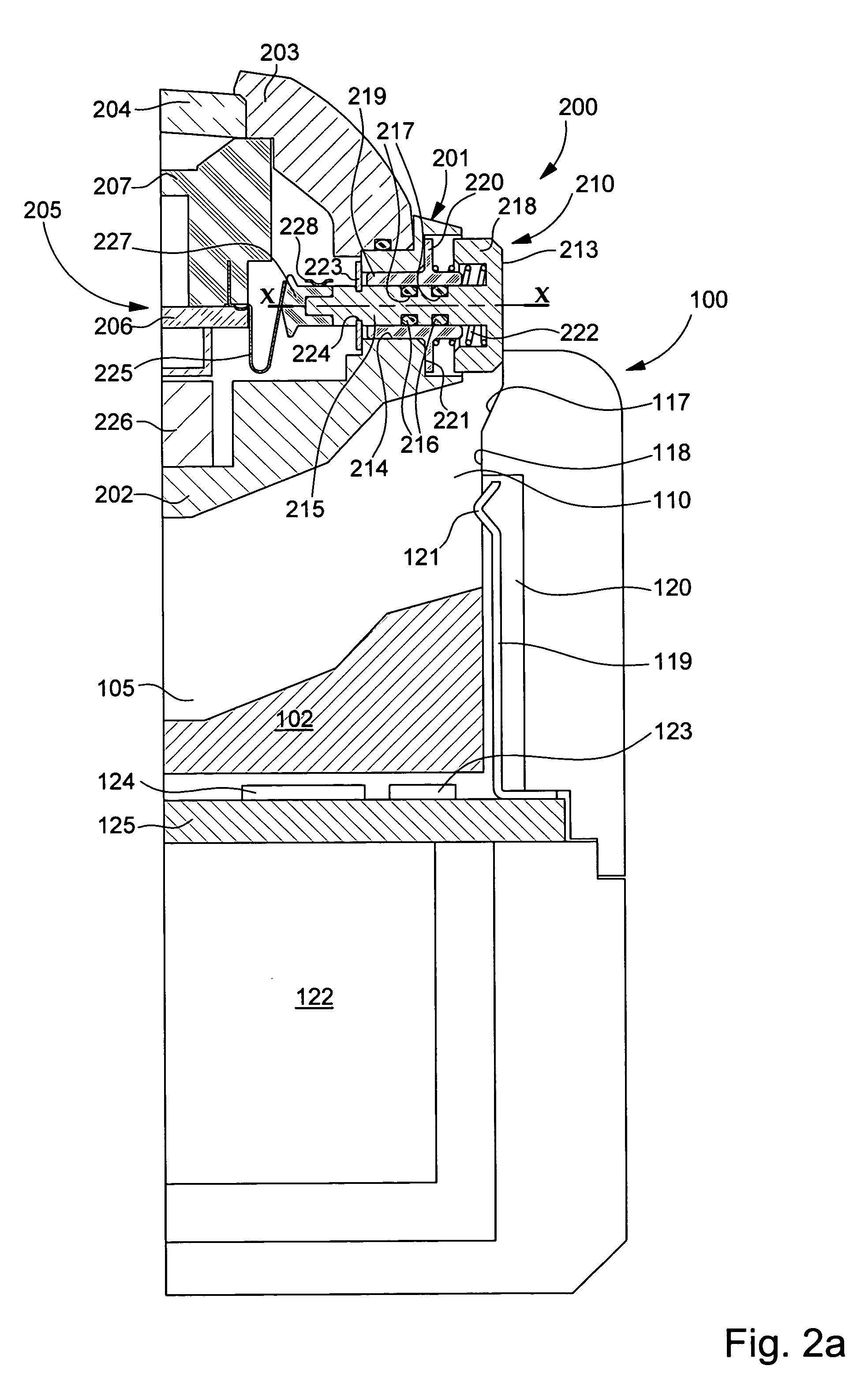
[0058]Thus, in this first embodiment, it will thus be understood that in FIG. 2a, i.e. in the non pushed-in position, retaining element 223 abuts middle part 202, at the periphery of assembly orifice 214. Consequently, in the non pushed-in position, the control member is earthed, stem 215 being electrically connected to middle part 202.

[0059]However, in FIG. 2b, i.e. in the pushed-in position, stem 215 is no longer electrically connected to middle part 202 because of the axial movement of retaining element 223, which accompanies the movement of stem 215, making it possible for electric signals to be transmitted via stem 215, which is then electrically connected to communication module 205 of the watch. It will be noted that in this pushed-in position, the control member is capable of operating like a conventional push-button, which is achieved by means of a first conventional electric contact and as an electric signal transmission member, which is achieved by means of a second elect...

second embodiment

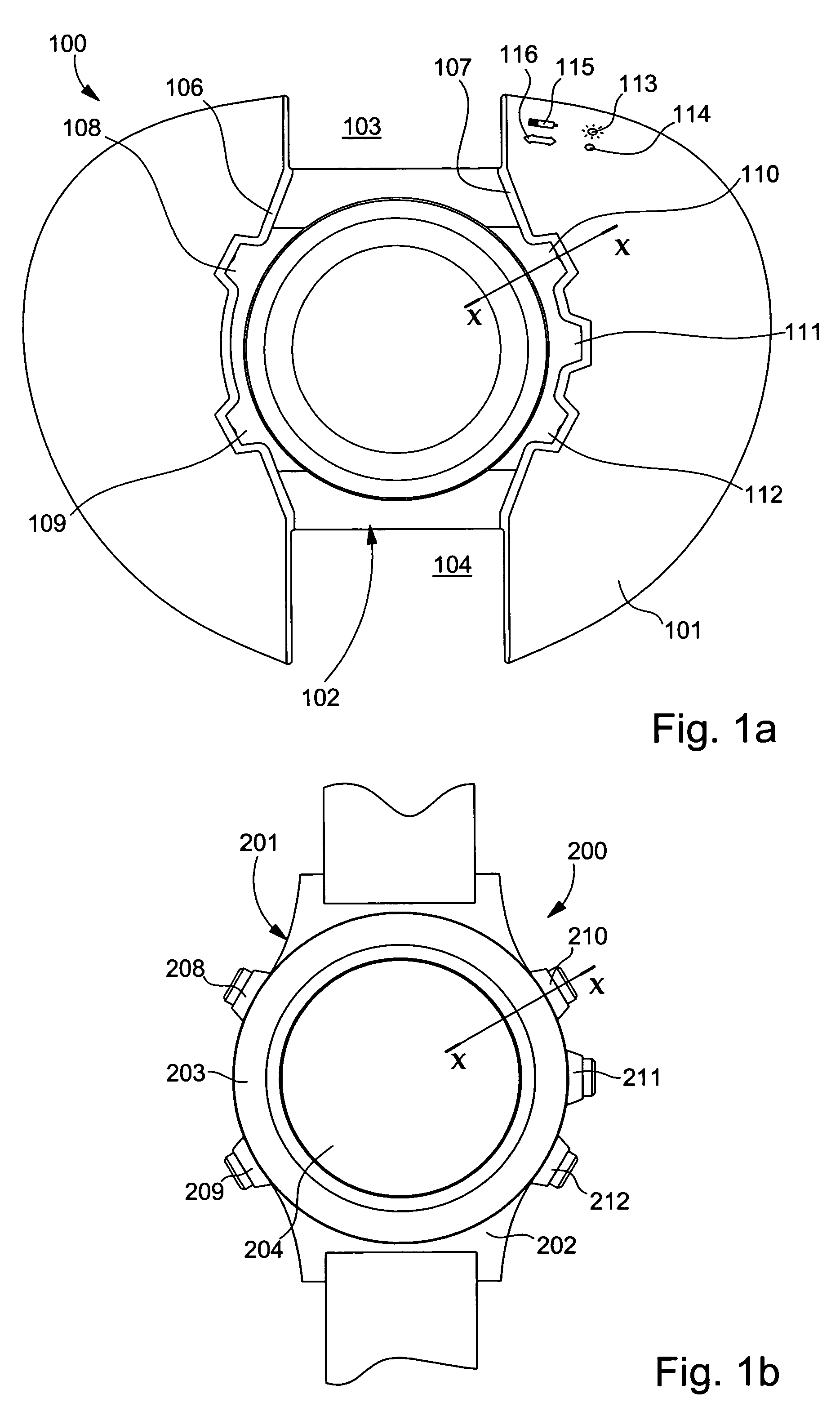
[0063]FIG. 4 shows a top view of an adaptor designated as a whole by the reference numeral 300, according to the invention. This adaptor 300 takes the form of a support 301 for a wristwatch defining on its top part a pattern cavity 302 dimensioned to receive the wristwatch (not shown). According to the example illustrated, support 301 is provided with first and second apertures 303 and 304 arranged on either side of pattern cavity 302 so as to allow the watch bracelet pass through and a third side aperture 305 capable of receiving a connecting element with an external communication unit, such as the mains or a personal computer, depending upon whether the adaptor is used respectively as a charger or communication interface.

[0064]Pattern cavity 302 preferably has a circular excavated portion 306 into which the back cover-middle part of the wristwatch is fitted. An aperture 308 is made in the bottom of this excavated portion, through which electric contact means 309 project so as to e...


PUM


Abstract

The invention concerns an adaptor (100) adapted to establish an electric connection with a portable electronic instrument (200) and to allow transmission of electric signals. The portable instrument is controlled via at least one control member (210) having first electric contact means (213) accessible from the exterior of the instrument. The control member is capable of occupying a first non pushed-in position and a second pushed-in position. The adaptor includes a support (101) having a pattern cavity (102) dimensioned to receive the instrument. The pattern cavity includes at least one housing (110) in which are arranged second electric contact means (119). The housing is dimensioned to receive the control member, such that, on the one hand, the control member is brought into the pushed-in position and, on the other hand, the first and second electric contacts are brought into contact, when the instrument is placed in the pattern cavity.

Description

[0001]This application claims priority from European Patent Application No. 03021457.1 filed Sep. 23, 2003, the entire disclosure of which is incorporated herein by reference.FIELD OF THE INVENTION[0002]The present invention concerns generally, a system for transmitting electric signals between a portable electronic instrument and an adaptor, such as for example, between a watch and a charger, or between a watch and a communication interface connected to an external communication unit, such as a personal computer. The invention concerns more particularly the means for establishing an electric connection between the portable electric instrument and the adaptor for transmitting electric signals from and / or to the portable instrument.BACKGROUND OF THE INVENTION[0003]Means for recharging the accumulator and respectively for charging or extracting data from a portable electronic instrument, such as a watch, are known in the prior art, particularly from EP Patent Application No. 1 109 084...

Claims


Application Information

Patent Timeline
Patent Type & Authority Patents(United States)
IPC IPC(8): H01R33/00H01R33/945H01R13/24H01R13/22H01R13/631G04G19/00G04G21/00G04G99/00H01R13/62H02J7/00
CPCH01R33/945H01R13/24H01R13/631H01R13/62
Inventor FERRI, YVANOESCH, YVES
Owner THE SWATCH GRP RES & DEVELONMENT LTD
Learn More