
Upward acting sectional door

a sectional door and door body technology, applied in the direction of door/window protective devices, wing accessories, shutters/movable grilles, etc., can solve the problems of reducing the payload of the trailer, presenting the same potential entrapment dangers of doors, and being unsuitable, etc., to achieve low maintenance, high strength, and light weight

Inactive Publication Date: 2005-10-18
OVERHEAD DOOR
View PDF42 Cites 16 Cited by
  • Summary
  • Abstract
  • Description
  • Claims
  • Application Information

AI Technical Summary

Benefits of technology

[0011]Therefore, an object of the present invention is to provide an upward acting sectional door in which the body of the door is an extruded corrugated polymer which provides an extent of insulation, without foamed insulating material and backing, as well as noise reduction for a quieter operating door than conventional sheet metal doors. Another object of the invention is to provide such a sectional door wherein the corrugated polymer has relatively high strength, is light weight, is low maintenance in not requiring painting, allows for expansion and contraction without warping the door, and can be produced at relatively low cost. A further object of the invention is to provide such a sectional door wherein the door has minimal intrusion interiorly of the door opening and may have a smooth interior surface which tends to avoid catching on objects in proximity to the interior surface which could cause damage to the object or the door. Yet another object of the invention is to provide such a sectional door wherein the polymer provides a movable pivot hinge function between the door sections.
[0012]Another object of the present invention is to provide such a sectional door having a body of corrugated polymer which can be coupled with an exterior metal cladding and / or tubular steel inserts to develop sufficient strength and rigidity for a particular door size and specifications. Yet a further object of the invention is to provide such a sectional door wherein end stiles, exterior metal cladding, and tubular steel inserts slide or snap into position to thereby eliminate the extensive use of fasteners or adhesives to interconnect the components of the door. Still another object of the invention is to provide such a sectional door which can be employed with conventional track configurations for sectional doors, but may mount the engaging rollers at substantially the centroid of the corrugated polymer body, whereby with the movable pivot hinge construction the door can negotiate a curved transitional track section between horizontal and vertical track section of approximately one half the normal radius.
[0022]An object of the present invention is to provide as an alternate a sectional pan door system which may be provided with or without insulation. Another object of the invention is to provide such an insulated sectional pan door wherein conventional foam insulation is mechanically retained by door panel components without the necessity for employing adhesives. A further object of the invention is to provide a sectional pan door which has minimal intrusion interiorly of the door opening, which works with a conventional track, and which can traverse a curved transitional track section having a greatly reduced radius without stressing the hinges or hinge areas. Yet another object of the invention is to provide a sectional pan door which is hinged at the end stiles, has pivotal closure assemblies extending the lateral extent of the panels at the edges to provide a pinch-resistant configuration, and may have spaced coupler elements to stabilize the pivot axis of the pivotal closure assemblies.
[0023]A further object of the invention is to provide a sectional pan door which does not have projecting hardware at the end stiles so that finger protection elements may be provided between the door edges and the vertical tracks. Another object of the invention is to provide a sectional pan door that can be adapted to a tension-type system for resisting wind loads through the roller assemblies and have a combined roller assembly and counterbalance system cable-securing device at the lower corners of the door. A still further object of the invention is to provide a sectional pan door that is sufficiently lightweight to be shipped completely assembled with a counterbalance system and motorized operator installed and connected, that is relatively inexpensive but strong, and that may be quickly and easily installed.

Problems solved by technology

These doors present the same potential entrapment dangers as the pivoting door.
These types of doors have been used on buildings but are not suitable as trailer doors in that the inside clearance space needed to open and close the door would significantly decrease the payload of the trailer.
Further, if the cargo shifted during transit, the door could be jammed in the closed position.
While increasing headroom or decreasing the hang down of the door into the door opening, these doors are somewhat flimsy and noisy to operate.
Moreover, the inability to move the plates through a conventional transitional radius necessitates the use of large diameter drive rollers on either side of the door consuming significant interior space.
The bending of the plates around the drive rollers causes undesirable stress on the plates and precludes tolerance to above-normal wind pressure.
Pinch-resistant sectional doors have been developed with integrally formed section interfaces that eliminate the finger and hand entrapping gaps, but these doors still require additional hardware to perform this function.
As a further disadvantage, sectional doors generally have hinges and other hardware mounted on the interior of the door.
If used as a trailer door, this hardware may damage cargo within the trailer or interfere with door movement.
But, due to the shorter height of the slats, a large number of slats are necessary to cover the door opening resulting in the rolling door being heavier and more expensive than sectional doors.
These doors also require extensive headroom to store the rolled up door when the door is in the open position.
The large number of slats also increases the time necessary to manufacture and assemble these doors.
Assembly is complicated by the fact that these doors require the slats to be individually longitudinally interlaced.
This interlacing also results in an interconnection which transmits force between slats so that even a localized impact can result in damage to a number of adjacent panels.
As will be appreciated, the addition of plastic insulating material increases the weight and complexity of the door, thereby increasing the cost to the manufacturer and the time necessary to manufacture the door.
Further, these rolling door designs normally have fixed pivot points with no provision for reducing stresses in the area of the hinges.
These known designs require expensive equipment of considerable size, particularly to process a double car width door section.
These angular movements of the sections alter the force required to move the door and put stress on the hinge and hinge mounting area.
This type of hinge design is more costly and care must be taken during the extrusion process to assure adequate bonding or encapsulation of the different polymers used to produce the hinge.

Method used


Image

  • Upward acting sectional door
  • Upward acting sectional door
  • Upward acting sectional door

Examples


Embodiment Construction

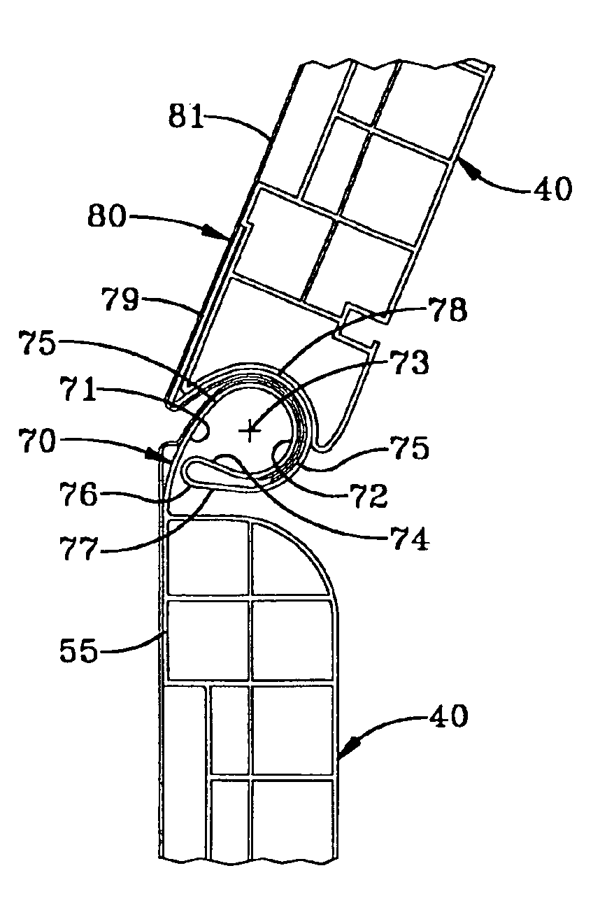
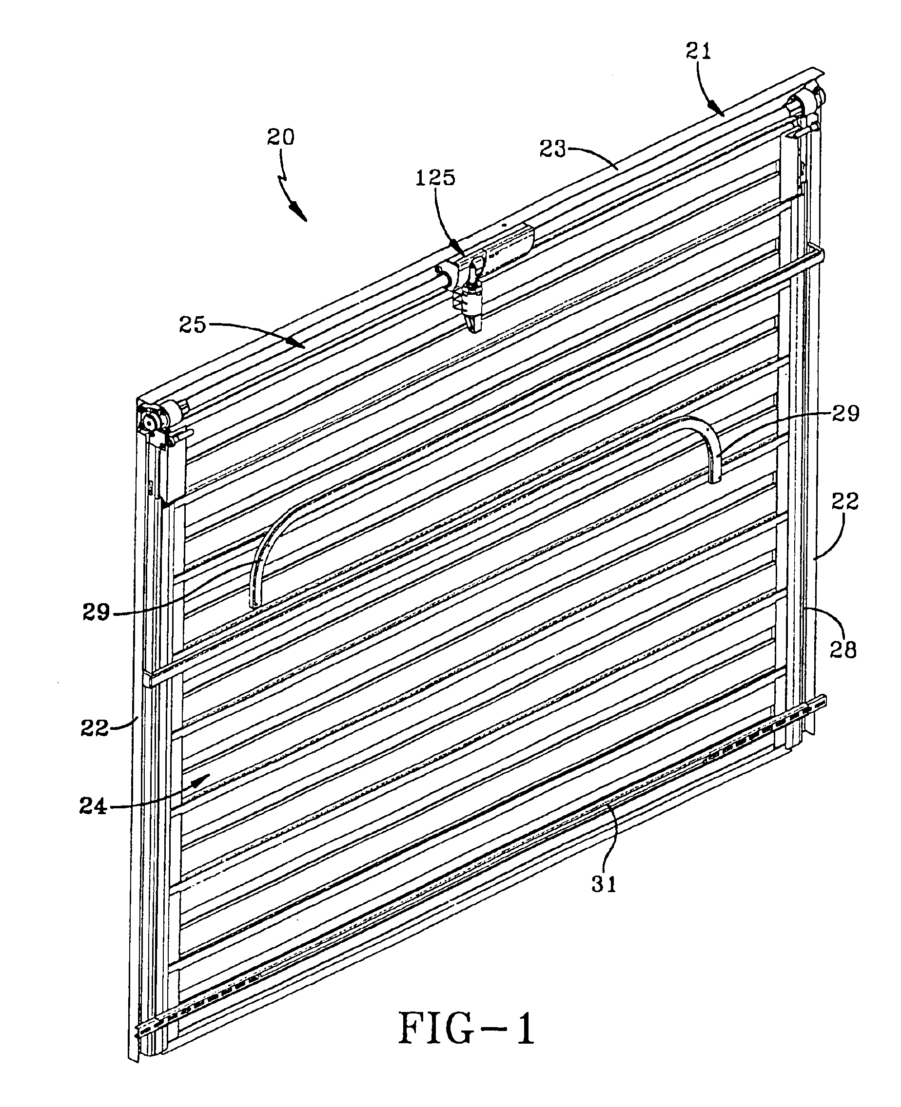
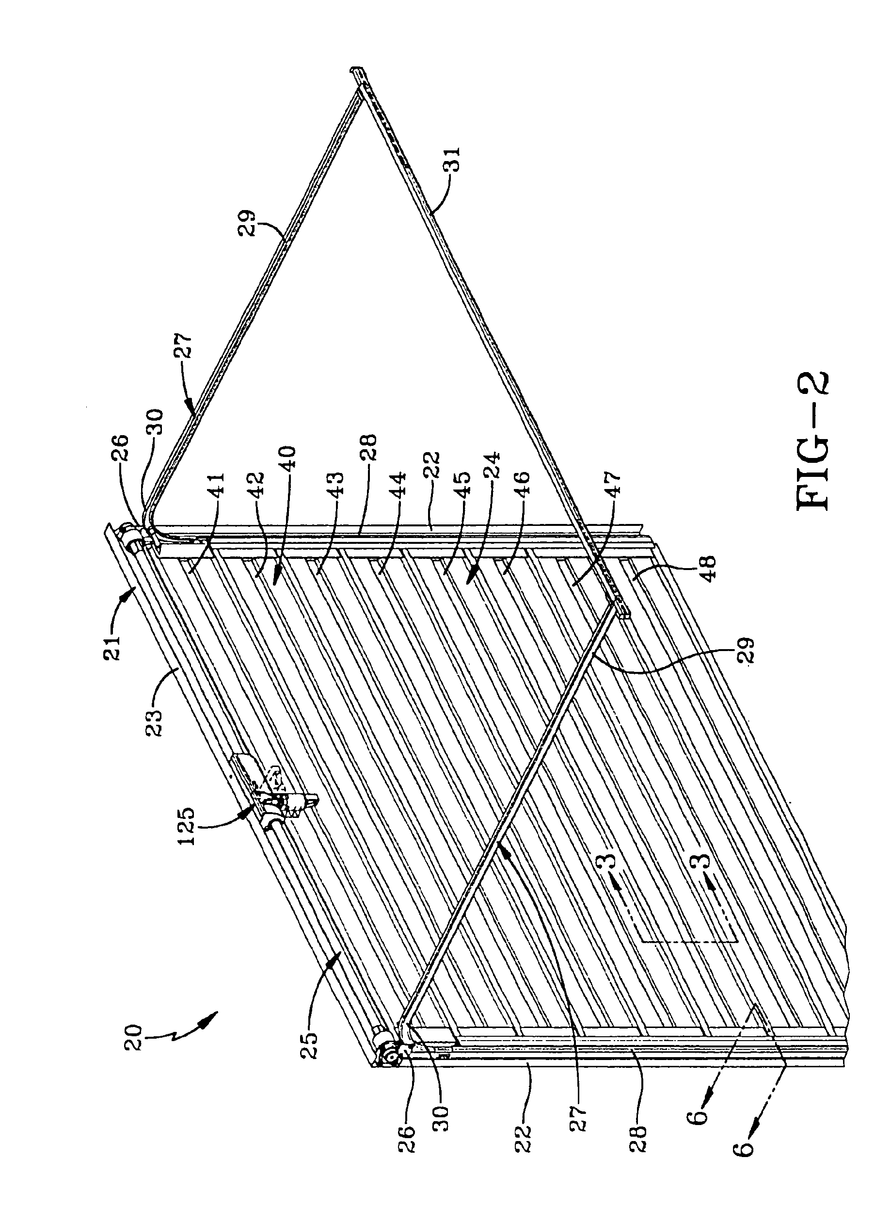
[0048]An upward acting metal cladded sectional door system embodying concepts of the present invention is generally indicated by the numeral 20 in FIG. 1 of the drawings. The door system 20 is positioned and mounted for opening and closing movement in a building or trailer by a peripheral door frame, generally indicated by the numeral 21. The frame 21 consists of a pair of spaced vertical track framers 22, 22 that, as seen in FIGS. 1 and 2, are generally parallel and extend vertically upwardly relative to a supporting surface such as a floor or the bed of a trailer (not shown). The vertical track framers 22, 22 are spaced and joined proximate their vertical upper extremity by a header framer 23 to thereby define the generally inverted U-shaped frame 21 for mounting a door, generally indicated by the numeral 24. Frame 21 may be constructed of metal or other relatively high strength, rigid material for purposes of reinforcement, attachment to a building or vehicle, and facilitating th...


PUM

PropertyMeasurementUnit
heightaaaaaaaaaa
heightaaaaaaaaaa
heightaaaaaaaaaa

Abstract

An upwardly acting sectional door (24), including a plurality of panels (40), body portions (50) of the panels constructed of a flexible polymeric material and having a front surface (55), a cladding (80) covering the front surface of the body portions and having hooks (83, 84) at the upper and lower edges thereof, a hinge member (51) at an edge of the body portion operatively engaging the hooks of adjacent of the panels to provide relative pivotal motion between adjacent panels. Another embodiment is an upwardly acting sectional pan door (224) including, a plurality of panels (240), facers (250) of the panels defining a front surface of the door and having cooperatively engaging couplers (270) at the upper and lower edges thereof; stiles (280) at the ends of the facers receiving and attached to the facers, and hinge assemblies (290) located at the end stiles to provide relative pivotal motion between the stiles and the couplers of adjacent panels.

Description

[0001]This application is a divisional of U.S. Ser. No. 09 / 710,253 filed on Nov. 10, 2000 now U.S. Pat. No. 6,672,362. 37 C.F.R. §1.78(a)(2).TECHNICAL FIELD[0002]The present invention relates to upward acting sectional doors. More particularly, the present invention relates to an upward acting sectional door having a flexibly hinged plastic core with metal cladding or a pan door with or without insulation. More particularly, the present invention relates to an upward acting sectional door having integral hinges that allow the door to pass through a very short transitional radius, a metal cladded exterior surface, interior insulation, if desired, and the capability of being packaged substantially preassembled, complete with a counterbalance system and operator installed.BACKGROUND ART[0003]There are numerous doors that are vertically oriented in the closed position and store in an open overhead position that are used as doors for buildings and trailers.[0004]One common construction i...

Claims


Application Information

Patent Timeline
Patent Type & Authority Patents(United States)
IPC IPC(8): E05D15/24E05F15/16E05D15/16E06B3/32E06B3/48E06B9/58E06B9/15E06B9/11E05D1/04E05D1/00E06B9/06
CPCE05F15/686E05D15/165E05D15/24E05D15/242E06B3/485E06B3/486E06B9/15E06B9/582E05D1/04E05Y2201/22E05Y2201/238E05Y2201/434E05Y2800/41E05Y2900/106E06B2009/587E05Y2600/11Y10T16/3803Y10T16/525E05D13/1261E05Y2900/00
Inventor MULLET, WILLIS J.RUSNAK, GREGORY M.
Owner OVERHEAD DOOR
Learn More