
Tunable MEMS capacitor

a capacitor and tunable technology, applied in the field of tunable capacitors, can solve the problems of reducing or degrading the quality of the capacitor, and achieve the effects of facilitating the attachment of appropriate electrical leads, high quality or q/q-factor, and facilitating the making of electrical connections

Inactive Publication Date: 2005-10-11
MEMX
View PDF11 Cites 20 Cited by
  • Summary
  • Abstract
  • Description
  • Claims
  • Application Information

AI Technical Summary

Benefits of technology

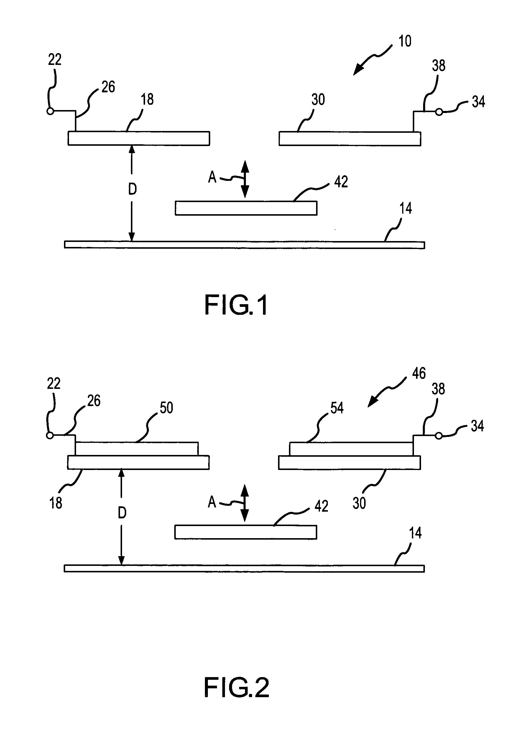
[0010]Electrical contact may be established with the above-noted first and second conductors (e.g., by bonding a first electrical lead directly to the first conductor and by bonding a separate second electrical lead directly to the second conductor). There is then no need for the electrical path to be through any of the support columns, posts, or anchors that may be used to dispose the first and second capacitor electrodes in a fixed, stationary position above the substrate in the first dimension. Disposing the first conductor on an upper surface of the first conductor electrode and disposing the second conductor on an upper surface of the second conductor electrode may facilitate this attachment of appropriate electrical leads, may in general facilitate making an electrical connection with the first and second conductors in a desired manner, and may provide other advantages (e.g., allowing the tunable capacitor to be fabricated by surface micromachining, specifically to allow the first and second conductors to be deposited after the various structural and sacrificial layers have been formed / patterned by surface micromachining).
[0011]The tunable capacitor of the first aspect may have a desirably high quality or Q / Q-factor, including when using a more resistive material for the first and second capacitor electrodes. In this regard, the resistance of the noted first and second conductors should be less than, and more preferably substantially less than, the resistance of the corresponding first and second capacitor electrodes in order to be able to achieve a desirably high quality for the tunable capacitor. Utilizing the first and second conductors thereby allows the first and second capacitor electrodes to be fabricated from a higher resistance material, such as polysilicon and which is commonly used in the fabrication of microstructures by surface micromachining, and yet still be able to realize a desirably high quality for the tunable capacitor of the first aspect.
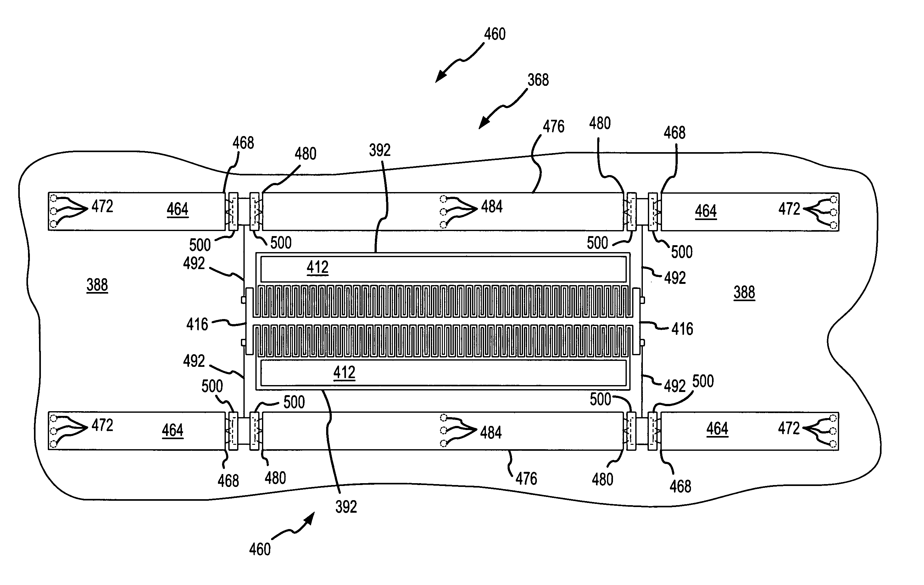
[0015]In one embodiment of the subject first aspect, the first and second capacitor electrodes of the tunable capacitor of the first aspect are fabricated from a common structural layer by surface micromachining (e.g., a structural layer that is disposed a common distance above a substrate). In another embodiment, both the first and second capacitor electrodes and the tuning element are fabricated from a common structural layer by surface micromachining. This reduces the potential for misalignment of the tuning element relative to the first and second capacitor electrodes by allowing a single mask to simultaneously define both the first and second capacitor electrodes, as well as the tuning element. One way that allows the tuning element and both the first and second capacitor electrodes to be fabricated from a common structural layer by surface micromachining is by utilizing an elevation system that biases the tuning element further away from the substrate after the tunable capacitor has been released at the end of the surface micromachining operation (e.g., after an etchant has been used to remove all or a portion of sacrificial material used in the fabrication of the tunable capacitor by surface micromachining).
[0032]A sixth aspect of the present invention is embodied by a tunable capacitor that includes a substrate, typically first and second capacitor plates or electrodes (only one may be required for a given application), and a movable tuning element. A plurality of lifters are interconnected with the tuning element and bias the tuning element away from the substrate. A travel limiter is associated with each such lifter to limit the maximum spacing between the tuning element and a substrate by constraining movement of the lifter beyond a certain distance above the substrate.

Problems solved by technology

In cases where the electrical signal to a capacitor electrode is directed through such a suspension spring, the quality of the capacitor is typically degraded or reduced because of the increased series resistance caused by the configuration of suspension spring.

Method used


Image

  • Tunable MEMS capacitor
  • Tunable MEMS capacitor
  • Tunable MEMS capacitor

Examples


Embodiment Construction

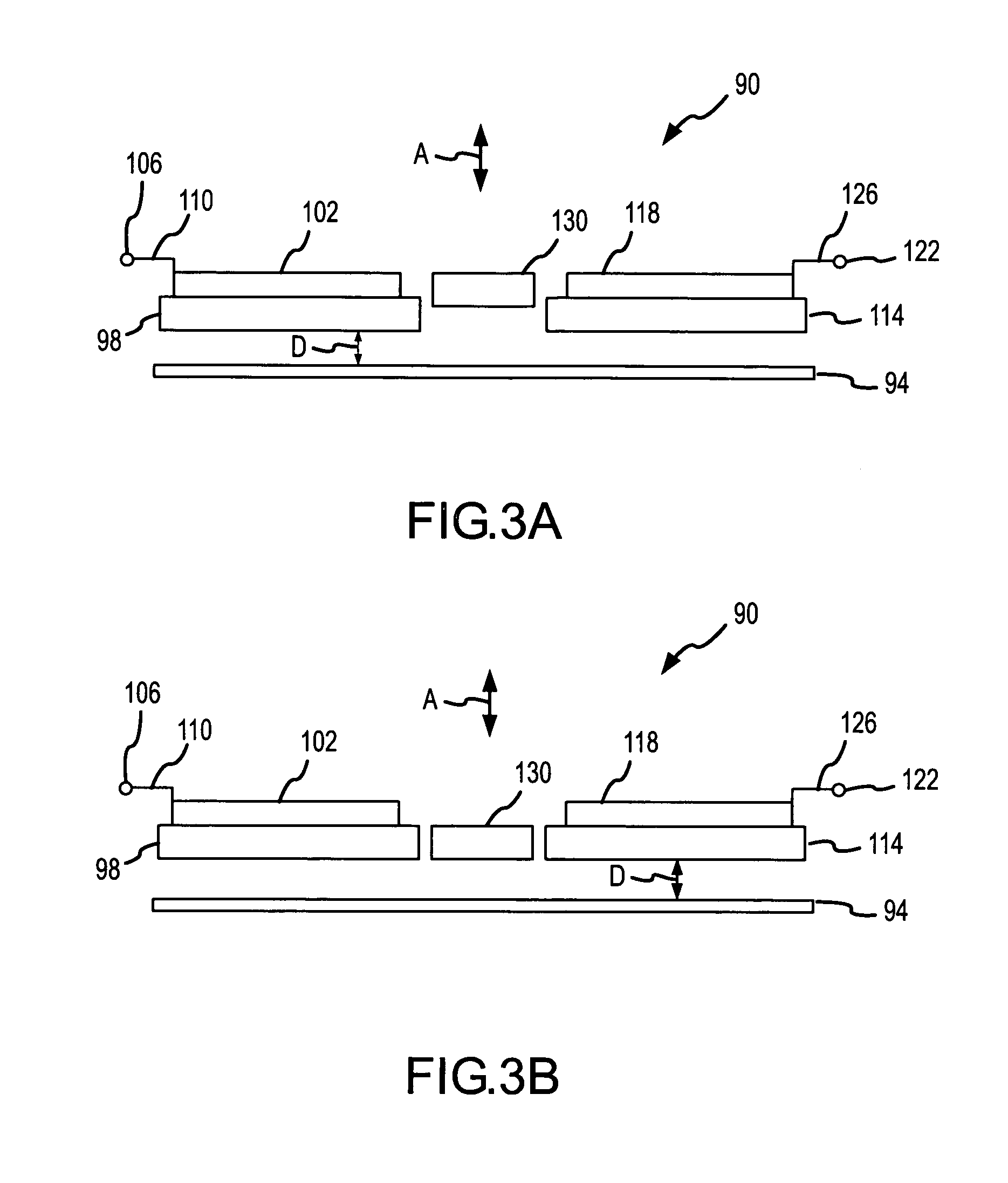
[0080]The present invention will now be described in relation to the accompanying drawings which at least assist in illustrating its various pertinent features. Various embodiments of tunable capacitors will be described herein. Each of these tunable capacitors may be fabricated by one or more appropriate microfabrication technologies, such as micromachining. Surface micromachining is the currently preferred fabrication technique for each of these tunable capacitors.

[0081]One embodiment of a tunable capacitor is illustrated in FIG. 1 and is identified by reference numeral 10. The tunable capacitor 10 is fabricated on / from a substrate 14 that is suitable for surface micromachining and that is the ultimate supporting structure of the resulting tunable capacitor 10. Fundamental components of the tunable capacitor 10 include a first capacitor electrode 18, a second capacitor electrode 30, and a tuning element 42. The first capacitor electrode 18, the second capacitor electrode 30, and t...


PUM


Abstract

Various embodiments of tunable capacitors are disclosed. One embodiment is in the form of a tunable capacitor (368) having a pair of stationary capacitor electrodes (392) that are fixed to and disposed the same distance above a substrate (388) in the vertical dimension. A tuning element (416) is suspended above the substrate (388) by an elevation system (460) that accommodates movement of the tuning element (416) in the vertical dimension. Changing the capacitance of the tunable capacitor (368) is accomplished by moving the tuning element (416) in the vertical dimension.

Description

CROSS REFERENCE TO RELATED APPLICATIONS[0001]This patent application claims priority under 35 U.S.C. §119 to U.S. Provisional Patent Application Ser. No. 60 / 523,933, that is entitled “TUNABLE MEMS CAPACITOR,” that was filed on Nov. 21, 2003, and the entire disclosure of which is incorporated by reference in its entirety herein.FIELD OF THE INVENTION[0002]The present invention generally relates to the field of tunable capacitors and, more particularly to a tunable capacitor that uses a pair of stationary, coplanar capacitor electrodes, as well as a tuning element that is movable (e.g., orthogonally) relative to these capacitor electrodes to vary the capacitance.BACKGROUND OF THE INVENTION[0003]One way to establish the capacitance of what is commonly referred to as a parallel plate capacitor is by changing the spacing between the capacitor plates or electrodes. There are capacitors of this type that may be tuned (to vary the capacitance) by changing the spacing between the capacitor e...

Claims


Application Information

Patent Timeline
IPC IPC(8): H01G5/00H01G5/14
CPCH01G5/145H03J2200/39H01G5/00
Inventor RODGERS, M. STEVEN
Owner MEMX
Learn More