Magnetic tape cartridge

a technology of magnetic tape and release pads, which is applied in the field of magnetic tape cartridges, can solve the problems of difficult to ensure the positioning of lock release pins of release pads, and defective assembly of release pads

Inactive Publication Date: 2005-10-11
FUJIFILM CORP +1
View PDF16 Cites 5 Cited by
  • Summary
  • Abstract
  • Description
  • Claims
  • Application Information

AI Technical Summary

Benefits of technology

[0021]According to the above structure of the magnetic tape cartridge, upon assembling the release pad with respect to the cup-shaped hub of the reel, the flank of the release pad extending from each corner downwardly through the respective lock releasing pins of the release pad ensures an assembling clearance between each corner of the release pad and the inner periphery of the flange arranged at the open side of the cup-shaped hub. Therefore, the release pad is inserted into the cup-shaped hub in a substantially non-tilted manner. Since the release pad is inserted into the cup-shaped hub while retaining a substantially horizontal posture that has been set previously, each lock releasing pin is reliably positioned with respect to the corresponding through-hole formed at the periphery of the bottom surface of the cup-shaped hub, so that the assembling robot ensures assembly of the release pad with respect to the cup-shaped hub.
[0028]According to the above structure of the magnetic tape cartridge, upon assembling the release pad with respect to the cup-shaped hub of the reel, likewise the conventional magnetic tape cartridge, the release pad is inserted into the cup-shaped hub from one side (edge) of the pad body with the front side (edge) thereof being lowered, and thereafter the rear side is lowered to gradually reduce the inclination angle of the release pad. At the same time, positioning is carried out between two of the front side lock releasing pins and the corresponding through-holes formed in the bottom surface of the cup-shaped hub. When doing so, because the flank is provided at the upper peripheral edge of the pad body and proximately to each lock releasing pin, an assembling clearance is secured between one front side (edge) of the pad body and the ribs projecting from the inner periphery of the cup-shaped hub. As the result, an interference between one front edge of the pad body and the ribs at the inner periphery of the cup-shaped hub is prevented, and so a reliable positioning is carried out between two of the front side lock releasing pins of the release pad and the through-holes formed in the bottom surface of the cup-shaped hub. When the release pad is dropped onto the bottom surface of the cup-shaped hub while retaining the relative position of the release pad, the lock releasing pins pierce through the corresponding through-holes of the cup-shaped hub so as to ensure the assembly of the release pad and the cup-shaped hub.
[0030]According to the above structure of the magnetic tape cartridge, the pad body is pinched in a reliable manner with the use of a pair of pinch chucks of the assembling robot.

Problems solved by technology

However, since the through-holes are arranged proximately to the inner peripheral wall of the cup-shaped hub pursuant to a circumferential arrangement having a certain diameter defined by LTO standard, it is difficult to ensure positioning of the lock releasing pins of the release pad, which are inserted into the cup-shaped hub in a tilted manner, with respect to the through-holes of the reel.
If the assembly is carried out by the use of an assembling robot, the release pad would be assembled defectively.
Therefore, when the release pad is inserted into the cup-shaped hub from one side (edge) of the pad body with the front side (edge) thereof being lowered, one front side (edge) of the pad body abuts to the ribs and positioning of the two lock releasing pins with respect to the corresponding through-holes would be insufficient, leading to defective assembly of the release pad.
This is more serious when assembly of the release pad is carried out by the use of an assembling robot.
For this reason, calculating the central points of the square holes 11D and the lower end surfaces 14D that are out of position from the certain regular position becomes complicated and it is difficult to prepare an image processing program.

Method used


Image

  • Magnetic tape cartridge
  • Magnetic tape cartridge
  • Magnetic tape cartridge

Examples


first embodiment

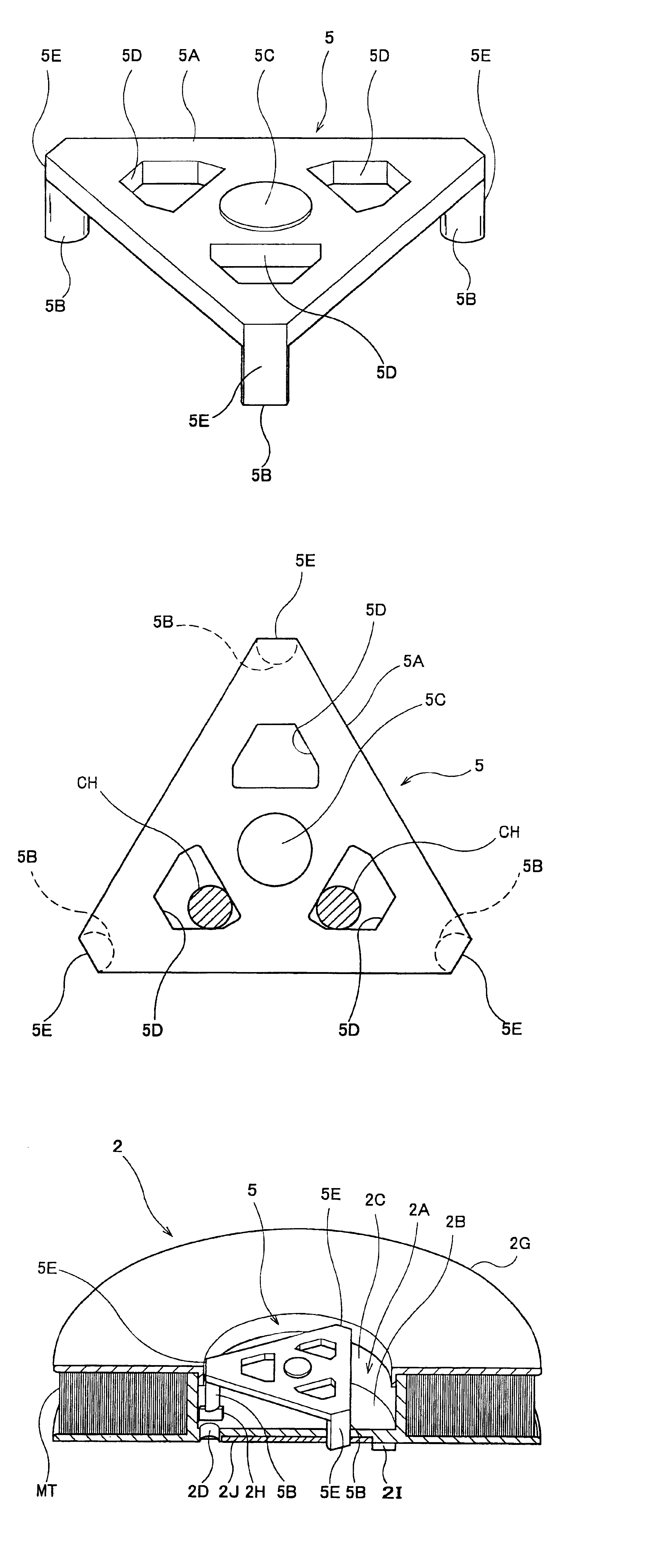
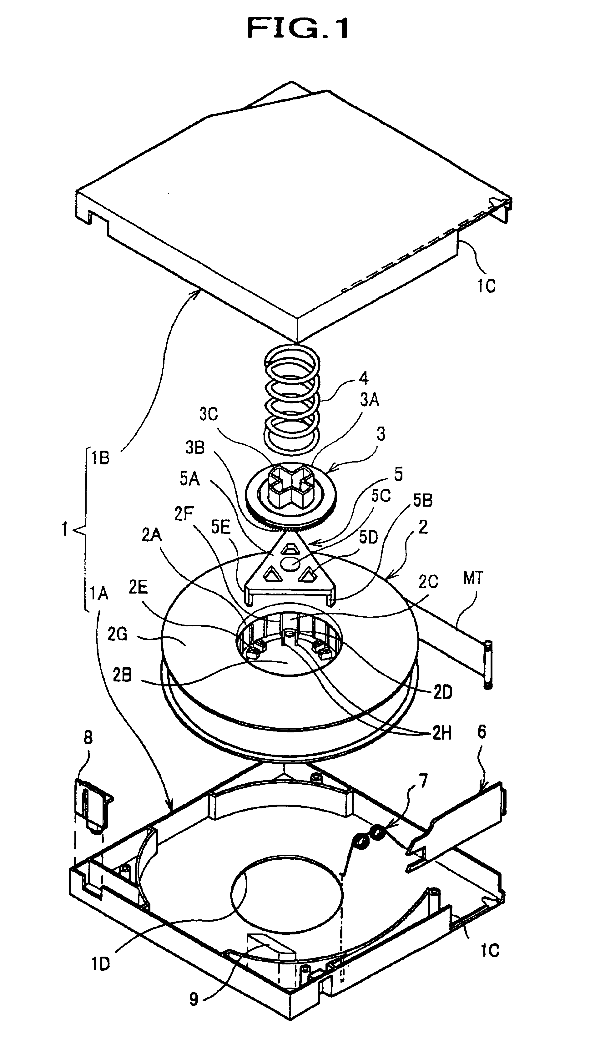
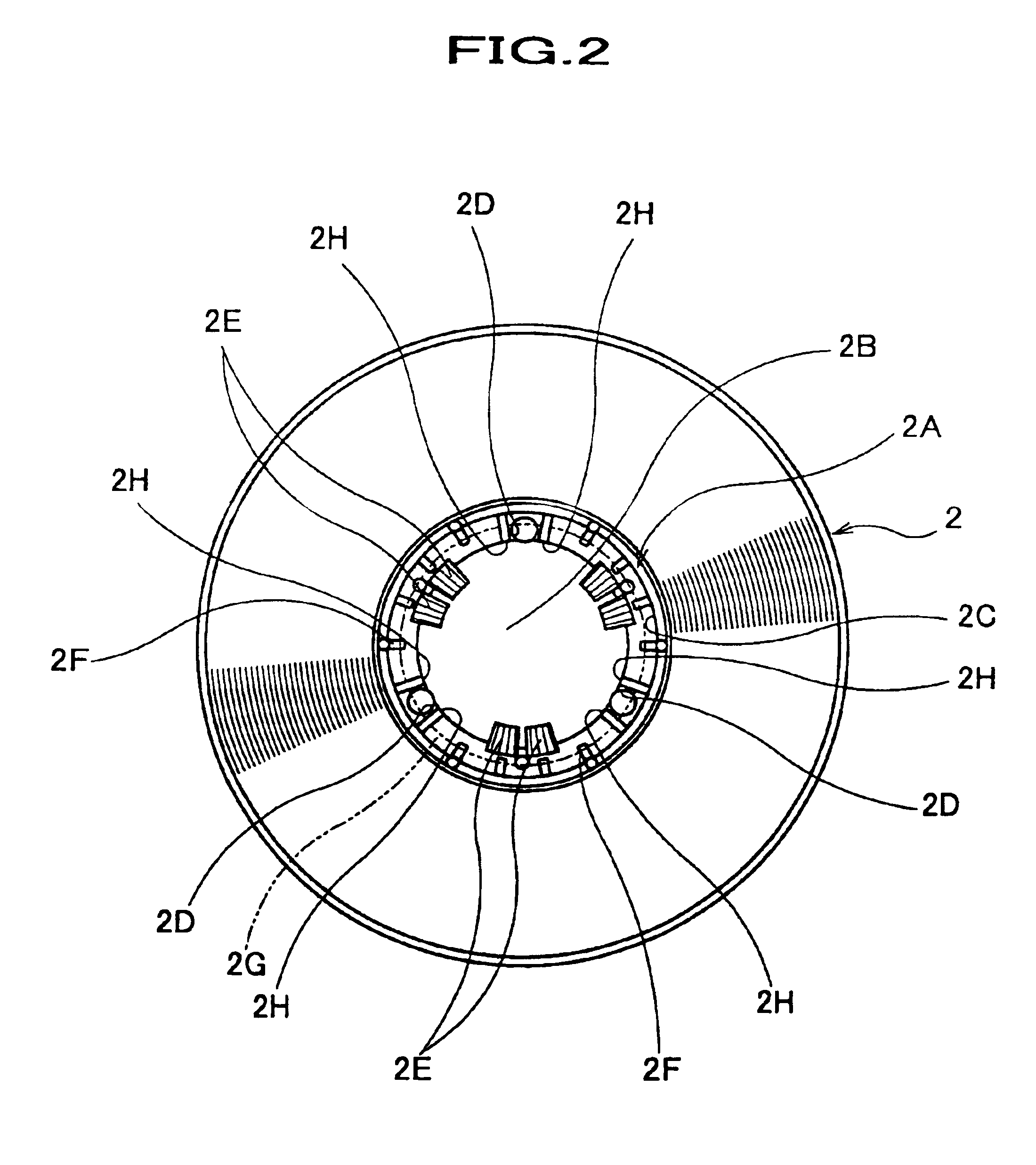
[0054]A magnetic tape cartridge according to a first embodiment will be described with reference to FIGS. 1 through 6. According to this magnetic tape cartridge, in order to ensure assembly of a release pad, the release pad is provided with a flank extending from each corner of a pad body through the respective lock releasing pins. As the drawings to be referred herein, FIG. 1 is an exploded perspective view illustrating structural elements of a magnetic tape cartridge according to the first embodiment of the present invention, FIG. 2 is a plan view illustrating an internal structure of a cup-shaped hub of a reel shown in FIG. 1, and FIG. 3 is a perspective view illustrating a release pad shown in FIG. 1.

[0055]The magnetic tape cartridge according to the first embodiment satisfies the LTO standard. As shown in FIG. 1, the magnetic tape cartridge comprises a cartridge case 1 separately formed by a lower half 1A and an upper half 1B, a single reel 2 previously winding a magnetic tape ...

second embodiment

[0067]A magnetic tape cartridge according to a second embodiment of the present invention will be described with reference to FIGS. 7 through 11. According to this magnetic tape cartridge, in order to ensure assembly of a release pad, a pad body of the release pad is provided with a flank at its upper peripheral edge. As the drawings to be referred herein, FIG. 7 is an exploded perspective view illustrating structural elements of a magnetic tape cartridge according to the second embodiment of the present invention, FIG. 8 is an enlarged perspective view illustrating a release pad shown in FIG. 7, and FIG. 9 is an enlarged plan view illustrating the release pad.

[0068]Likewise the magnetic tape cartridge according to the first embodiment shown in FIG. 1, the magnetic tape cartridge according to the second embodiment satisfies the LTO standard. As shown in FIG. 7, the magnetic tape cartridge comprises a cartridge case 1 separately formed by a lower half 1A and an upper half 1B, a singl...

third embodiment

[0079]A magnetic tape cartridge according to a third embodiment of the present invention will be described with reference to FIGS. 12 through 14. According to this magnetic tape cartridge, in order to facilitate relative positioning between a release pad and a reel, at least an outer profile of each through-hole formed in a bottom surface of a cup-shaped hub of the reel or an outer profile of a lower end surface of each lock releasing pin of the release pad is circular in shape. As the drawings to be referred herein, FIG. 12 is an exploded perspective view illustrating structural elements of a magnetic tape cartridge according to the third embodiment of the present invention, and FIG. 13 is an enlarged exploded perspective view illustrating a main structure of the magnetic tape cartridge shown in FIG. 12.

[0080]Likewise the magnetic tape cartridge according to the first embodiment shown in FIG. 1, the magnetic tape cartridge according to the third embodiment satisfies the LTO standar...


PUM


Abstract

A magnetic tape cartridge comprises: a reel 2 around which a magnetic tape MT is wound; a cartridge case 1 for accommodating the reel 2 in a locked state; and a release pad 5 inserted into a cup-shaped hub 2A of the reel 2 in a locked state of the reel 2. The release pad 5 includes a pad body 5A having a plurality of corners to be faced proximately to the inner peripheral surface 2C of the cup-shaped hub 2A, and a plurality of lock releasing pins 5B projecting downwardly from a bottom surface of the pad body 5A at the respective corners and inserted through a bottom surface of the cup-shaped hub 2A. The release pad 5 is provided with a flank 5E extending from each corner downwardly through the respective lock release pin 5B so that an assembling clearance is formed with respect to an inner periphery of a flange 2G position in an open side of the cup-shaped hub 2A.

Description

FIELD OF THE INVENTION[0001]The present invention relates to a magnetic tape cartridge. More particularly, the present invention relates to a magnetic tape cartridge, which ensures assembly of a release pad that releases a locked state of the reel.BACKGROUND OF THE INVENTION[0002]As a magnetic tape cartridge utilized for an external memory medium for backup of a data of a computer and the like, there is a conventionally known magnetic tape cartridge that satisfies a so-called LTO (Linear Tape Open) standard. Such a magnetic tape cartridge comprises a cartridge case separately formed by a lower half and an upper half, and a single reel winding a magnetic tape is accommodated in the cartridge case. A tape-leading opening for pulling out the magnetic tape is provided at one side of the cartridge case extending over the lower and the upper halves, and a leader pin connected at the end of the magnetic tape is engaged at the tape-leading opening in such a manner that the magnetic tape is ...

Claims


Application Information

Patent Timeline
IPC IPC(8): G11B23/107G11B23/04G11B23/08G11B23/087G11B23/113
CPCG11B23/044G11B23/107
Inventor TSUYUKI, SEIJIYAMAMOTO, HIDETOSHISHIGA, HIDEAKIOKUTSU, NAOKI
Owner FUJIFILM CORP
Why Eureka
Try Eureka