
Switching power supply unit and controller IC thereof

a technology of power supply unit and controller, which is applied in the direction of electric variable regulation, process and machine control, instruments, etc., can solve the problems of difficulty in realizing all control operations, start-up failures, and difficulty for actual apparatuses to perform all control operations, so as to prevent the occurrence of rush current and start-up failure, and increase the dc voltage

Active Publication Date: 2005-10-11
ROHM CO LTD
View PDF7 Cites 58 Cited by
  • Summary
  • Abstract
  • Description
  • Claims
  • Application Information

AI Technical Summary

Benefits of technology

[0026]The object of the invention is to provide a switching power supply unit having a low-voltage operating block and a high-voltage operating block to produce a higher DC voltage from a low power supply voltage, and a controller IC thereof, which prevents occurrence of a rush current and a start-up failure at switching.
[0027]Another object of the invention is to shorten overall start-up time by smooth switching control operation.

Problems solved by technology

In such a case, the higher DC voltage might be produced from a switching power supply unit, however, in many cases, it might be difficult for an actual apparatus to perform all the control operations, including a PWM control operation, at a low power supply voltage.
However, an actual apparatus often encounters difficulty in performing all control operations such as PWM control operation at a low voltage on the order of 1.5 volts or thereabouts.
When these operations are repeated, an start-up failure might arise.
This might bring about adverse effect to the battery power supply or cause an inconvenience of a large drop in the battery voltage Vbat.
Hence, there arises a problem that a rush current flows at the time of start-up.
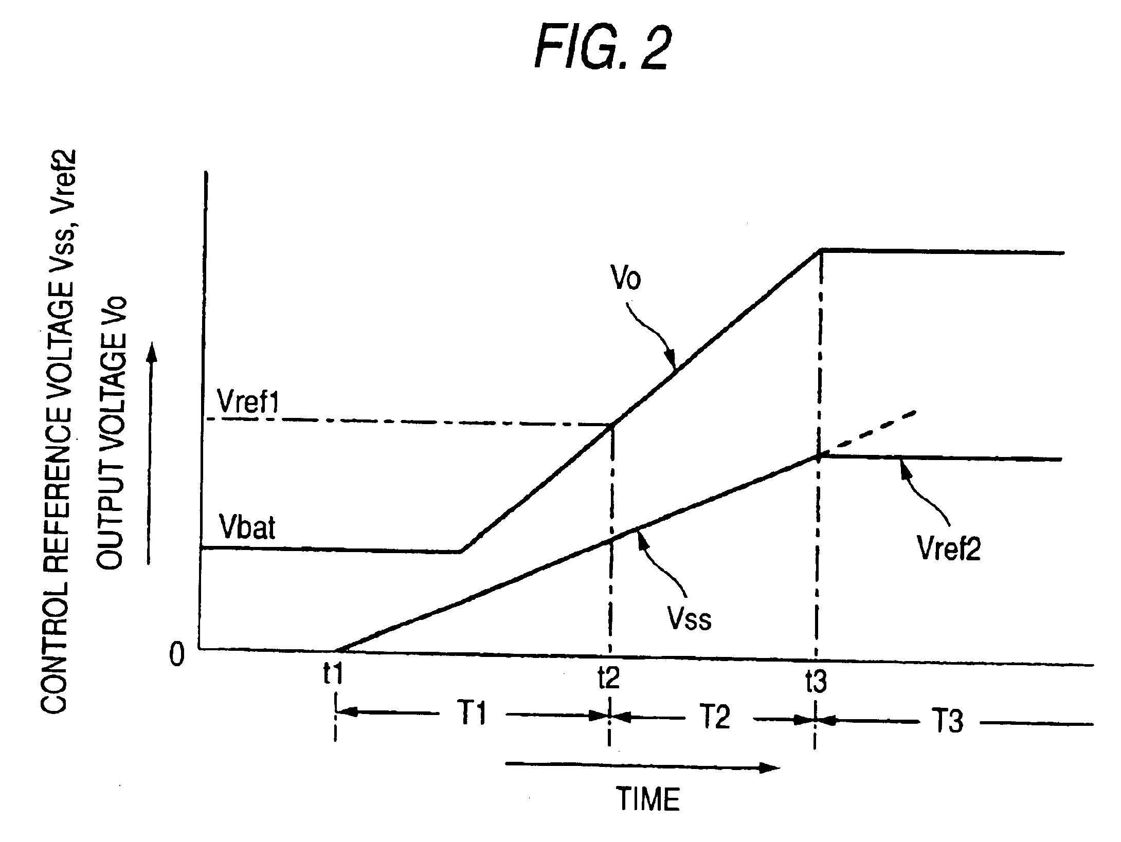
There may also arise a problem that ringing in the output voltage Vo occurs around at the timing of t3 when the control reference voltage to be compared with the triangular wave signal CT shifts from the SS voltage Vss to the error output signal EO.

Method used


Image

  • Switching power supply unit and controller IC thereof
  • Switching power supply unit and controller IC thereof
  • Switching power supply unit and controller IC thereof

Examples


Embodiment Construction

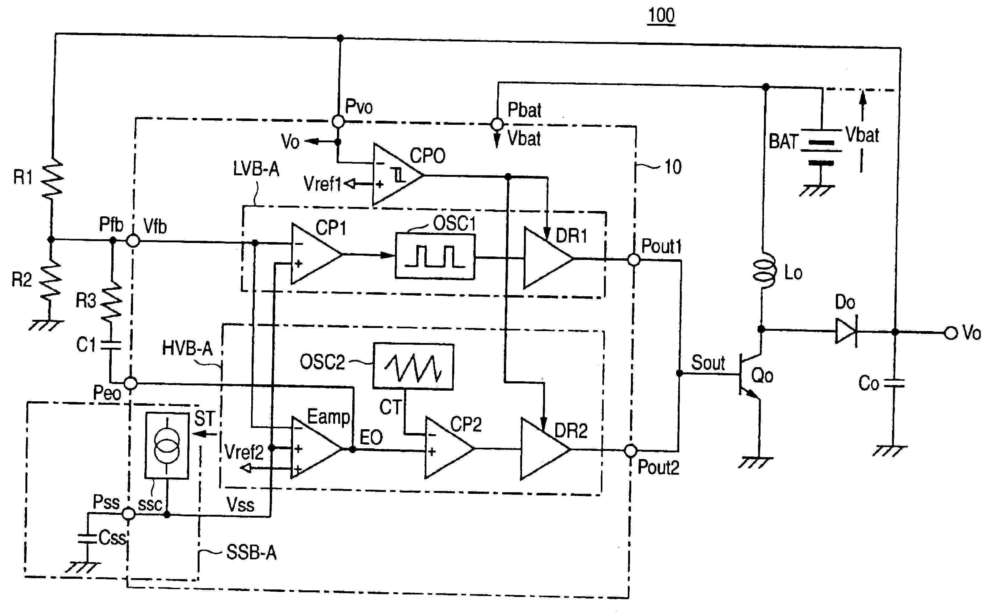
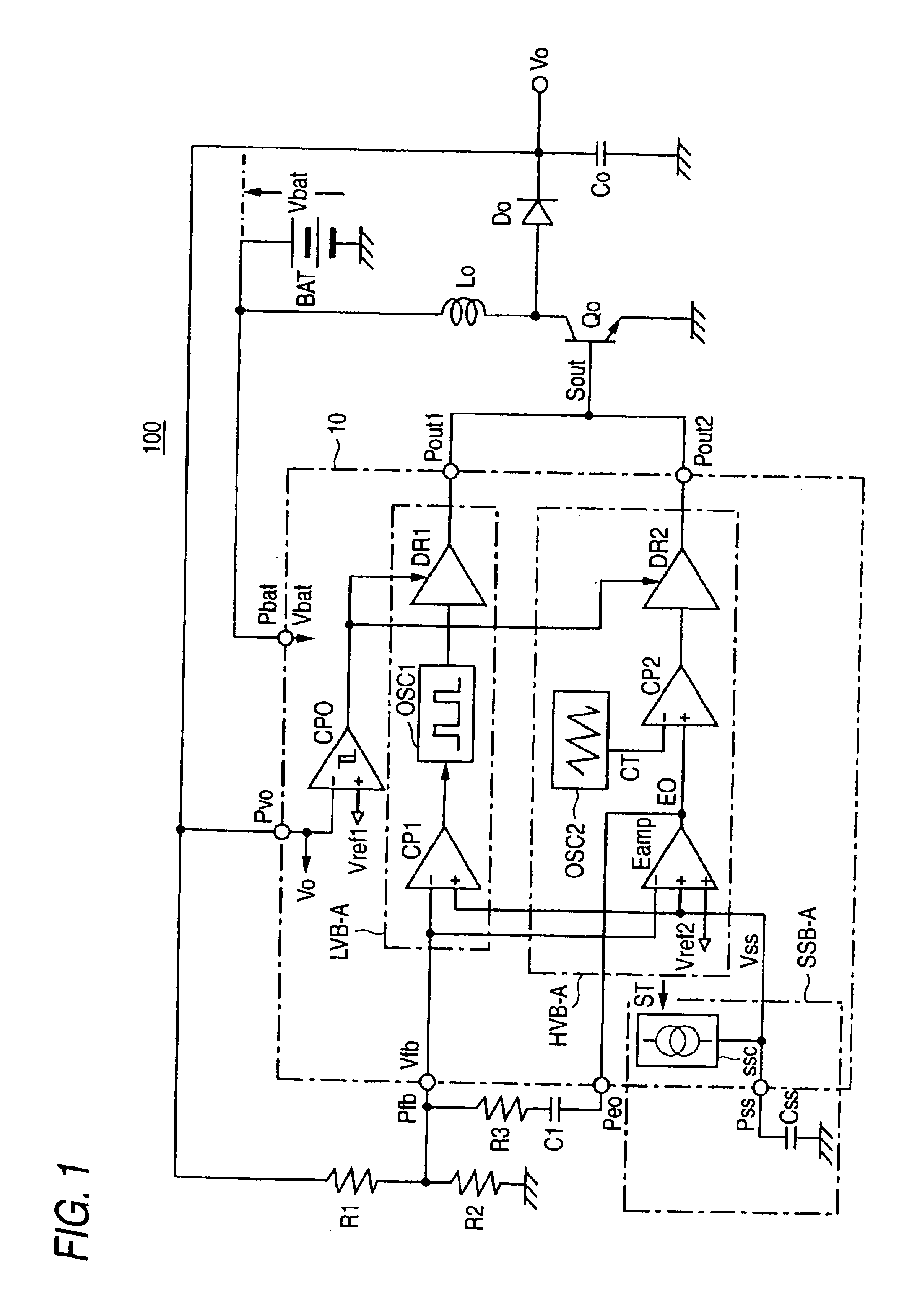
[0037]An embodiment of a switching power supply unit according to the invention and a controller IC thereof will be described hereinbelow by reference to the drawings. FIG. 1 is a view showing the configuration of a switching power supply unit according to a first embodiment of the invention. FIG. 2 is a view schematically showing a characteristic of the switching power supply unit at the time of start-up.

[0038]The switching power supply unit 100 shown in FIG. 1 differs from the conventional switching power supply unit 200 shown in FIG. 3 in terms of a low-voltage operating block LVB-A, a high-voltage operating block HVB-A, and a soft start block SSB-A, which are in a controller IC 10. Other parts of the switching power supply unit 100 are identical with each other of the conventional switching power supply unit 200. Therefore, explanations are primarily given of differences between the switching power supply unit 100 of the invention and the conventional related-art switching power...


PUM


Abstract

A low-voltage operating block and a high-voltage operating block are controlled at the same soft start voltage as that employed at the time of start-up. At a point in time at which an output DC voltage has reached an expected value, a control signal of the low-voltage operating block is switched to a control signal of the high-voltage operating block. As a result, switching is smoothly performed without involvement of occurrence of a variation in the output voltage before and after switching operation. In a switching power supply unit having a low-voltage operating block and a high-voltage operating block, which are intended for producing a higher DC voltage from a low power supply voltage, it prevents occurrence of a rush current and a start-up failure, which would otherwise be caused by switching operation.

Description

BACKGROUND OF THE INVENTION[0001]1. Field of the Invention[0002]The invention relates to a switching power supply unit which switches input voltage to produce output voltage that is different from the input voltage, and to a controller IC thereof.[0003]2. Description of the Related Art[0004]In a portable cellular phone, a digital camera, a PDA, and a personal computer, a higher DC voltage is often required to be produced from a low power supply voltage such as a battery cell. In such a case, the higher DC voltage might be produced from a switching power supply unit, however, in many cases, it might be difficult for an actual apparatus to perform all the control operations, including a PWM control operation, at a low power supply voltage. For this reason, a conventional switching power supply unit is provided with a low-voltage operating block capable of operating at a low voltage within the range from 1.0 to 1.5 volts or thereabouts such as disclosed in JP-A-8-186980. In said refere...

Claims


Application Information

Patent Timeline
IPC IPC(8): H02J7/00H02M3/156H02M1/00H02M3/04H02M3/155H02M1/36
CPCH02J7/0065H02M3/156H02M1/36Y10S323/901H02J2207/20
Inventor HOSHINO, TAICHIOYAMA, EITARO
Owner ROHM CO LTD
Learn More