
Plastic expulsion process for forming hollow tubular products

a hollow tubular product and expulsion process technology, applied in the field of injection molding of plastic materials, can solve the problems of losing control of the gas, difficult to achieve difficulty in achieving sufficient gas penetration along the intended gas channel, etc., to achieve accurate control of the volume of plasti

Inactive Publication Date: 2005-10-11
CINPRES
View PDF77 Cites 14 Cited by
  • Summary
  • Abstract
  • Description
  • Claims
  • Application Information

AI Technical Summary

Benefits of technology

"The present invention provides an improved gas assisted plastic injection molding process for the production of plastic products, particularly hollow tubular components. The process allows for better control over the volume of plastic into the mold, resulting in more consistent wall thickness and reduced flow or weld marks. The process also reduces the amount of plastic needed and improves reproducibility. The gas assisted plastic injection molding process can be used with a wide range of plastic materials and can be adapted for multi-product cavity molds. The process provides a more efficient and effective means for molding plastic products."

Problems solved by technology

In the “full shot” process, it is sometimes difficult to achieve sufficient gas penetration along intended gas channels because there is insufficient volumetric shrinkage of the plastic to provide space for the gas.
In the “short shot” method, some moldings may also be difficult to fill with plastic and gas to the extremities of the molded article cavity.
If the shot volume is too little, the gas may break through the leading edge of the plastic material during filling, thereby losing control of the gas.
However, in order to use the method of this patent successfully, it is necessary to accurately control the shot volume for both “short shot” and “full shot” methods, because there is no resistance to prevent the plastic from flowing into and filling the overflow cavity before the gas is injected.
In both cases, it is not feasible to apply “packing pressure” by the molding machine because there is nothing to restrain the further flow of plastic.
In the “short shot” process, or when nearly filling the cavity in a “full shot” process, there may remain unsightly visible hesitation lines or marks on the molding surface at the position of the first plastic injection.

Method used


Image

  • Plastic expulsion process for forming hollow tubular products
  • Plastic expulsion process for forming hollow tubular products
  • Plastic expulsion process for forming hollow tubular products

Examples


Embodiment Construction

)

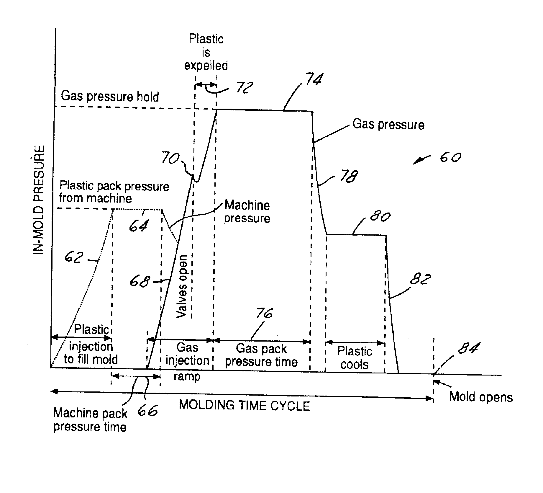
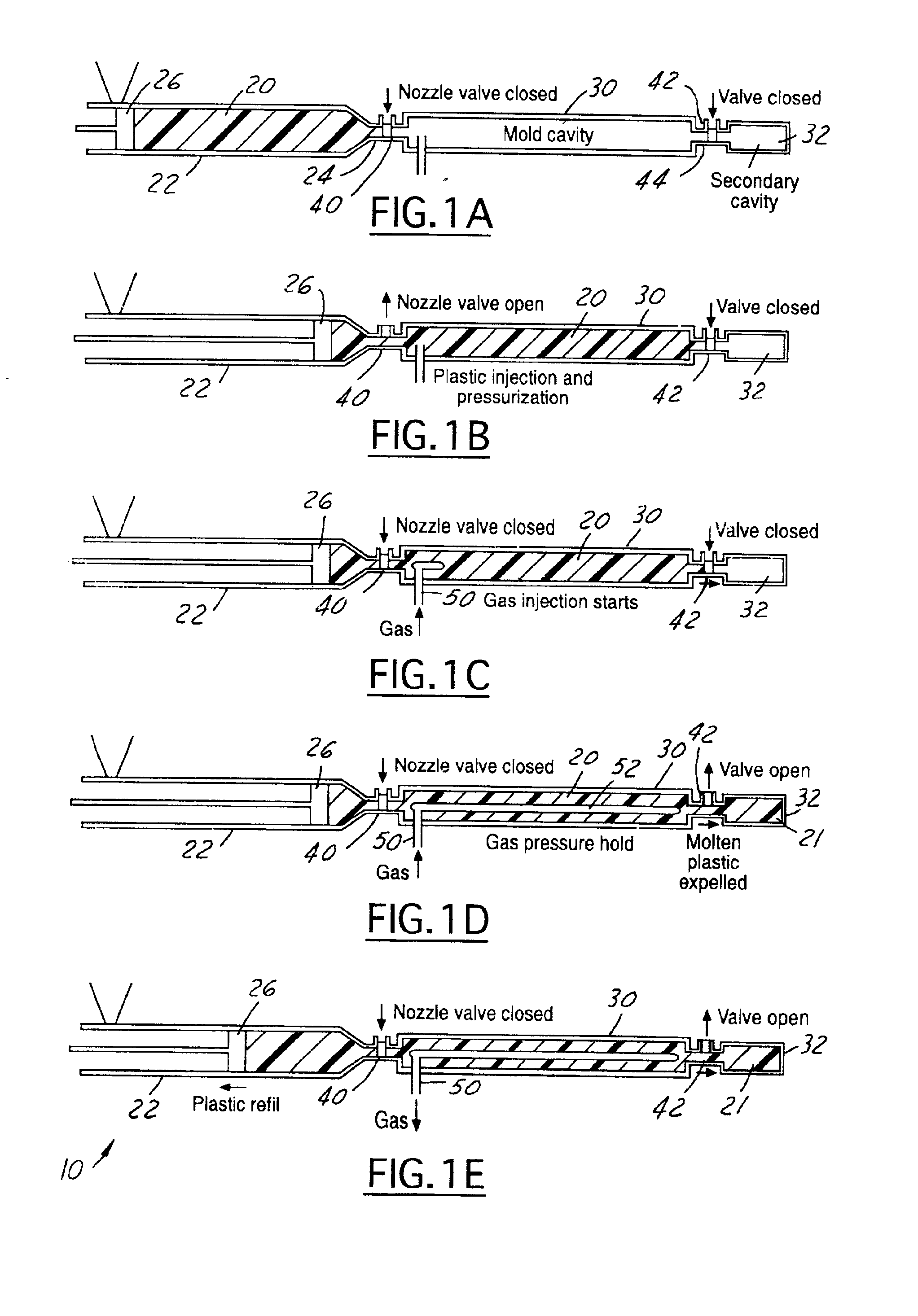
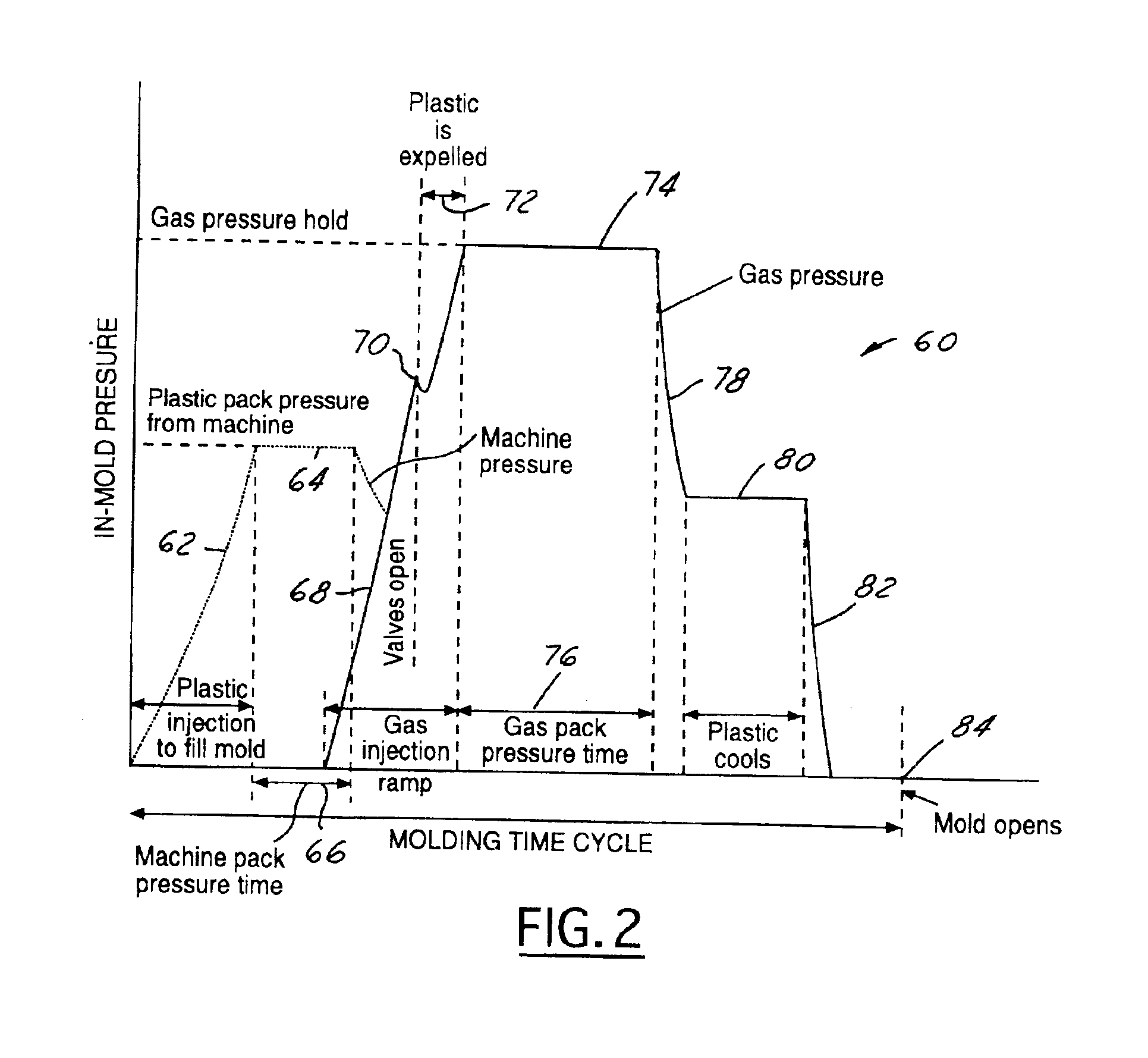
[0030]FIGS. 1A-1E illustrate the sequence of steps forming a preferred embodiment of the present invention. This process is referred to generally by the reference numeral 10 in the drawings. In FIG. 1A, a quantity of molten plastic material 20 is positioned in the barrel 22 of an injection molding machine (not shown). The injection molding machine can be of any conventional type and can expel the plastic material from the nozzle 24 of the barrel in any conventional manner, such as by a helical screw or a piston 26. Although a piston member 26 is shown and illustrated and described in FIGS. 1A-1E, it is to be understood that any conventional mechanism used to expel the plastic material from a barrel of an injection molding machine can be utilized.

[0031]As shown in FIG. 1A, the nozzle 24 of the injection molding machine is connected to a mold cavity 30. The mold cavity 30 is positioned in a conventional mold which in turn is positioned in a conventional molding machine (not shown). A...


PUM

PropertyMeasurementUnit
timeaaaaaaaaaa
included anglesaaaaaaaaaa
pressureaaaaaaaaaa

Abstract

A system and process for gas assisted plastic injection molding, particularly of hollow tubular components. The plastic material is injected into the mold cavity through an apex of a cone-shaped inlet configuration. After the molding pressure is held for a period of time, gas is injected into the plastic material and pressure is again held for a period of time, a valve member is opened allowing plastic to be expelled into a secondary cavity. The flow of the plastic and gas are controlled in an axial direction in order to prevent turbulence. The gas flow axially along the center of the tubular member allows the expulsion of plastic from the center uniformly along the length of the tube. In an alternative process, the gas is displaced axially into the barrel of the injection molding machine.

Description

CROSS REFERENCE TO RELATED APPLICATIONS[0001]This application is a continuation-in-part of U.S. patent application Ser. No. 09 / 902,354, filed on Jul. 10, 2001, and entitled “Plastic Expulsion Process.”TECHNICAL FIELD[0002]The present invention relates to the field of injection molding of plastic materials, and in particular to gas assisted molding.BACKGROUND OF THE INVENTION[0003]Injection molding of plastic materials is well known and widely practiced as a means of manufacturing an ever-increasing diversity of plastic components for industrial and consumer use. During the last two decades, versions of the process globally referred to as “gas assisted molding” have been developed and used to overcome some of the problems inherent in conventional molding, and to reduce costs and improve the quality of the final products.[0004]In conventional gas molding, a gas, such as nitrogen, is injected into the molten plastic material after it has entered the mold. The low viscosity gas flows in...

Claims


Application Information

Patent Timeline
Patent Type & Authority Patents(United States)
IPC IPC(8): B29C45/76B29C45/17
CPCB29C45/1711B29C45/762B29C2045/1712B29C2045/1713B29C2045/1719B29C2045/468
Inventor PEARSON, TERRENCE C.
Owner CINPRES
Learn More