
Three dimensional engineering of planar optical structures

a three-dimensional engineering and optical structure technology, applied in the direction of optical elements, instruments, active medium materials, etc., can solve the problems of further challenges, difficult introduction of different elements, either dopants or stoichiometric components, into desired compositions, etc., and achieve the effect of higher average index of refraction

Inactive Publication Date: 2005-10-04
NANOGRAM
View PDF72 Cites 120 Cited by
  • Summary
  • Abstract
  • Description
  • Claims
  • Application Information

AI Technical Summary

Benefits of technology

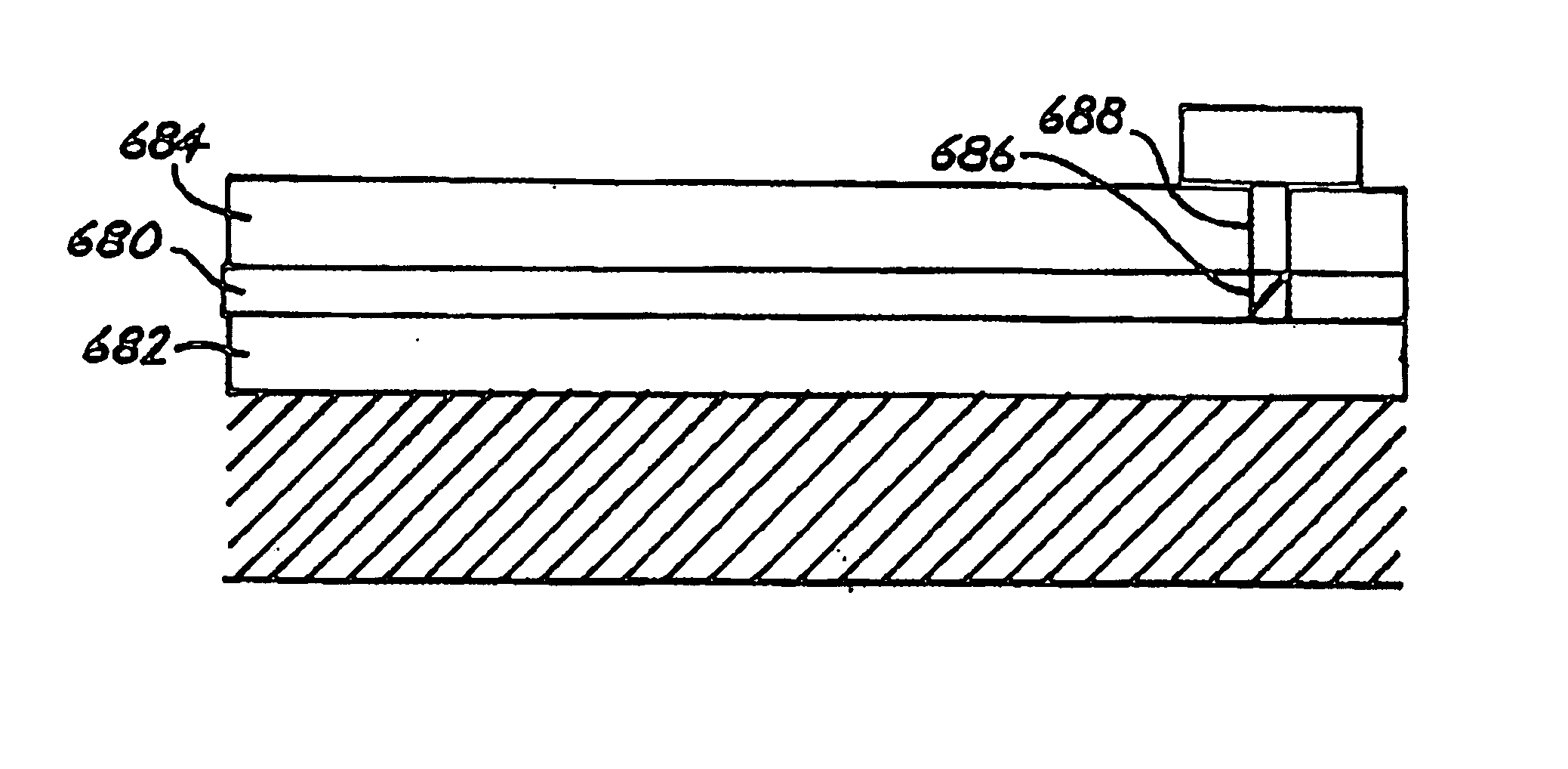
[0020]Also, the invention pertains to an optical device comprising a first cladding layer of optical material, a second cladding layer of optical material and a core of optical material. The core is adjacent to the first cladding layer and the second cladding layer and has a higher index-of-refraction than the cladding layers. One of the cladding layers has a localized band of tap material having an index-of-refraction intermediate between the core layer and the average index-of-refraction of the cladding layer with the localized band intersecting the core material. The tap material provides for the leakage of some light intensity into the tap material when light is transmitted through the core.

Problems solved by technology

The introduction of different elements, either dopants or stoichiometric components, into desired compositions can be difficult.
In particular, blending elements to form complex compositions for optical materials can be challenging.
Further challenges can result if particular complex compositions are to be located at particular locations within a structure.

Method used


Image

  • Three dimensional engineering of planar optical structures
  • Three dimensional engineering of planar optical structures
  • Three dimensional engineering of planar optical structures

Examples


Embodiment Construction

[0079]Complex optical structures incorporate controlled variation in composition and / or other physical properties affecting optical properties across the three dimensions of the structure. Generally, the optical structure has a planar extent orienting the structure and layers within the structure. The variation in optical properties can be along planes oriented along the planar extent of the structure and / or in direction(s) perpendicular to the plane(s). Thus, three dimensional variations in the optical properties can be achieved to create optical properties at selected locations to achieve desired optical responses. In particular, planar optical devices can be formed that are integrated in one, two or all three dimensions such that more complex integrated optical structures are possible. Also, composition gradients can be formed to provide transitions in the optical and / or the mechanical properties of the material.

[0080]In some embodiments, improved control over the placement of op...


PUM


Abstract

Three dimensional optical structures are described that can have various integrations between optical devices within and between layers of the optical structure. Optical turning elements can provide optical pathways between layers of optical devices. Methods are described that provide for great versatility on contouring optical materials throughout the optical structure. Various new optical devices are enabled by the improved optical processing approaches.

Description

FIELD OF THE INVENTION[0001]The invention relates to optical materials and planar optical structures. The planar optical structures, comprising multilayered structures, can comprise planar optical devices, comprising integrated optical devices. The optical properties within the planar optical structures can vary within the plane and perpendicular to the plane to achieve desired optical properties and integration. Specific optical devices can take advantage of the three dimensional engineering of the optical structure.BACKGROUND[0002]Presently used optical communication light wavelengths are from 1.3 to 1.6 microns. Optical waveguides, in fiber or planar form, generally have dimensions many times the wavelength. Thus, optical structures can have dimensions from a few microns to about 100 microns depending on optical mode requirements and other factors. Optical transmission generally is based on transmission through a higher index-of-refraction material in a core that is surrounded by...

Claims


Application Information

Patent Timeline
IPC IPC(8): H01S3/06H01S3/063H01S3/17H01S3/0941
CPCH01S3/0632H01S3/0635H01S3/0637H01S3/0941H01S3/176H01S3/2308
Inventor BI, XIANGXINNEVIS, ELIZABETH ANNEMOSSO, RONALD J.CHAPIN, MICHAEL EDWARDCHIRUVOLU, SHIVKUMARKHAN, SARDAR HYATKUMAR, SUJEETLOPEZ, HERMAN ADRIANHUY, NGUYEN TRAN THEHORNE, CRAIG RICHARDBRYAN, MICHAEL A.EUVRARD, ERIC
Owner NANOGRAM
Learn More