
Thin film magnetic head and method of manufacturing the same

a technology of magnetic head and thin film, which is applied in the field of thin film magnetic head, can solve the problems of insufficient strength of perpendicular magnetic field in view of future movement in areal recording density, which is expected to be further increased, and is not sure whether the structure of the magnetic pole can be actually manufactured and whether it is useful, so as to improve the recording performance

Active Publication Date: 2005-10-04
TDK CORPARATION
View PDF4 Cites 82 Cited by
  • Summary
  • Abstract
  • Description
  • Claims
  • Application Information

AI Technical Summary

Benefits of technology

[0010]In view of the foregoing, it is a first object of the invention to provide a thin film magnetic head capable of securing the strength of a perpendicular magnetic field and improving recording performance.
[0011]Moreover, it is a second object of the invention to provide a method of manufacturing a thin film magnetic head which can easily manufacture the thin film magnetic head of the invention by use of existing manufacturing techniques.

Problems solved by technology

However, in spite of various considerations of the structure of the main magnetic pole in conventional thin film magnetic heads using the perpendicular recording system, the strength of the perpendicular magnetic field is still not sufficient enough in view of future movement in areal recording density which is expected to be further increased.
However, a specific manufacturing method which is important to implement the structure of the magnetic pole is not described, so it is uncertain about whether the structure of the magnetic pole can be actually manufactured and whether it is useful.

Method used


Image

  • Thin film magnetic head and method of manufacturing the same
  • Thin film magnetic head and method of manufacturing the same
  • Thin film magnetic head and method of manufacturing the same

Examples


first embodiment

[First Embodiment]

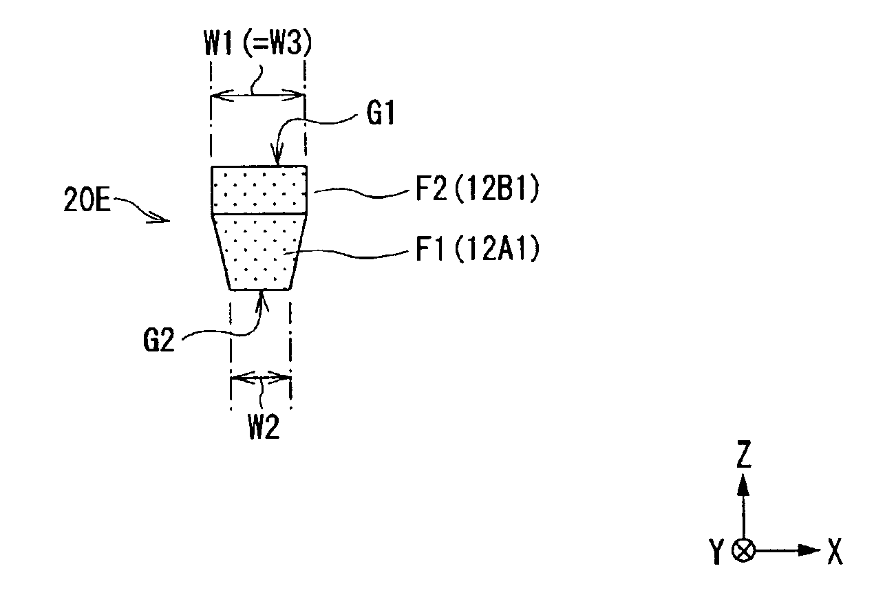
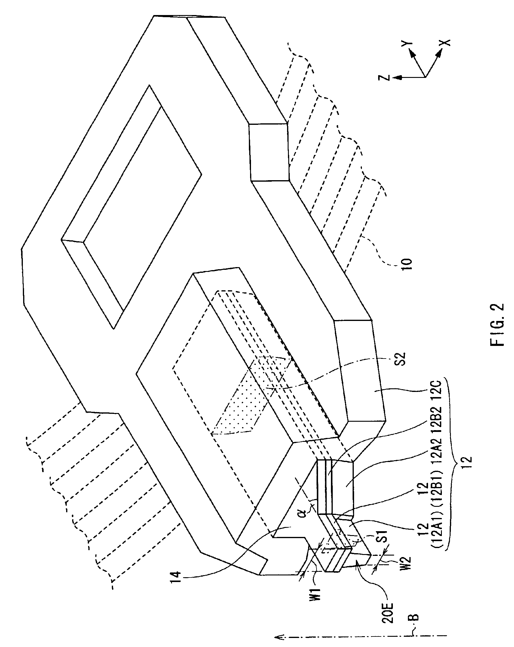
[0108]First of all, referring to FIGS. 1A through 3, the structure of a thin film magnetic head according to a first embodiment of the invention will be described below. FIGS. 1A and 1B show sectional views of the thin film magnetic head according to the embodiment. FIG. 2 shows an enlarged perspective view of a main part (a main magnetic pole) of the thin film magnetic head shown in FIGS. 1A and 1B. FIG. 3 shows an enlarged plan view of an exposed surface in the main magnetic pole shown in FIG. 2. FIG. 1A shows a sectional view parallel to an air bearing surface and FIG. 1B shows a sectional view perpendicular to the air bearing surface. An up arrow B in FIGS. 1A and 1B indicates a direction in which a recording medium moves relative to the thin film magnetic head, that is, a direction of movement of the recording medium.

[0109]In the following description, an X-axis direction, a Y-axis direction and a Z-axis direction in FIGS. 1A through 3 are expressed as “a widt...

second embodiment

[Second Embodiment]

[0176]Next, a second embodiment of the invention will be described below.

[0177]FIGS. 33 through 36 are views for describing a method of manufacturing a thin film magnetic head according to the second embodiment of the invention. In the method of manufacturing the thin film magnetic head according to the embodiment, the main part of the main magnetic pole is formed through etching instead of the two-step forming method described in the first embodiment. FIGS. 33 through 35 show sectional views of each step in the method of manufacturing the thin film magnetic head according to the embodiment, and FIG. 36 shows an enlarged perspective view of the main part (the main magnetic pole) of the thin film magnetic head manufactured through the method of manufacturing the thin film magnetic head according to the embodiment. In FIGS. 33 through FIG. 36, like components are denoted by like numerals as of the first embodiment.

[0178]At first, referring to FIG. 36, the structure ...


PUM


Abstract

Provided is a thin film magnetic head capable of ensuring the strength of a perpendicular magnetic field and improving recording performance. A bottom pole portion layer and a top pole portion layer constituting a part of a main magnetic pole are formed so that a cross sectional area of a complex including front end portions of the bottom pole portion layer and the top pole portion layer is smaller than a cross sectional area of a complex including rear end portions thereof, and a width of a top edge in an exposed surface is larger than a width of a bottom edge, and is equal to or larger than a width of the exposed surface in a middle position between the top edge and the bottom edge. In recording, magnetic fluxes flowing in a main magnetic pole are focused toward an air bearing surface, and are concentrated on the front end portion of the top pole portion layer which is a main emitting portion of the magnetic fluxes, so sufficient magnetic fluxes can be supplied to the air bearing surface.

Description

BACKGROUND OF THE INVENTION[0001]1. Field of the Invention[0002]The present invention relates to a thin film magnetic head having at least an inductive magnetic transducer for writing, and a method of manufacturing the same.[0003]2. Description of the Related Art[0004]In recent years, an improvement in performance of thin film magnetic heads has been sought in accordance with an increase in the areal recording density of hard disk drives. As magnetic recording systems applicable for the hard disk drives, for example, a longitudinal recording system that a signal magnetic field is oriented in an in-plane direction of a recording medium (a longitudinal direction) and a perpendicular recording system that the signal magnetic field is oriented in a direction perpendicular to the recording medium are well-known. At present, the longitudinal recording system is widely used, but the perpendicular recording system instead of the longitudinal recording system holds promise for future, becaus...

Claims


Application Information

Patent Timeline
IPC IPC(8): G11B5/31G11B5/39
CPCG11B5/3116G11B5/313G11B5/3163G11B5/3967
Inventor SATO, YOSHIKAZUMOTEGI, YUKOROPPONGI, TETSUYANOTSUKE, YASUYUKI
Owner TDK CORPARATION
Learn More