
Protective device with end of life indicator

a technology of protection device and indicator, which is applied in the direction of emergency protective arrangement for limiting excess voltage/current, circuit-breaking switches, instruments, etc., can solve the problems of limited current through this type of fault, parallel arc fault, and life-threatening electric shock hazards

Inactive Publication Date: 2005-10-04
PASS SEYMOUR
View PDF10 Cites 67 Cited by
  • Summary
  • Abstract
  • Description
  • Claims
  • Application Information

AI Technical Summary

Benefits of technology

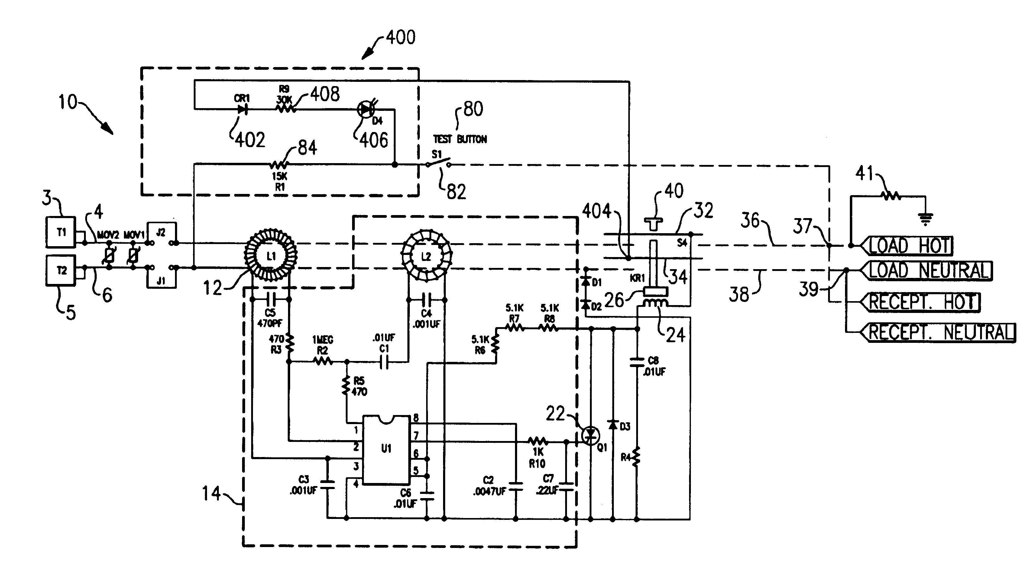
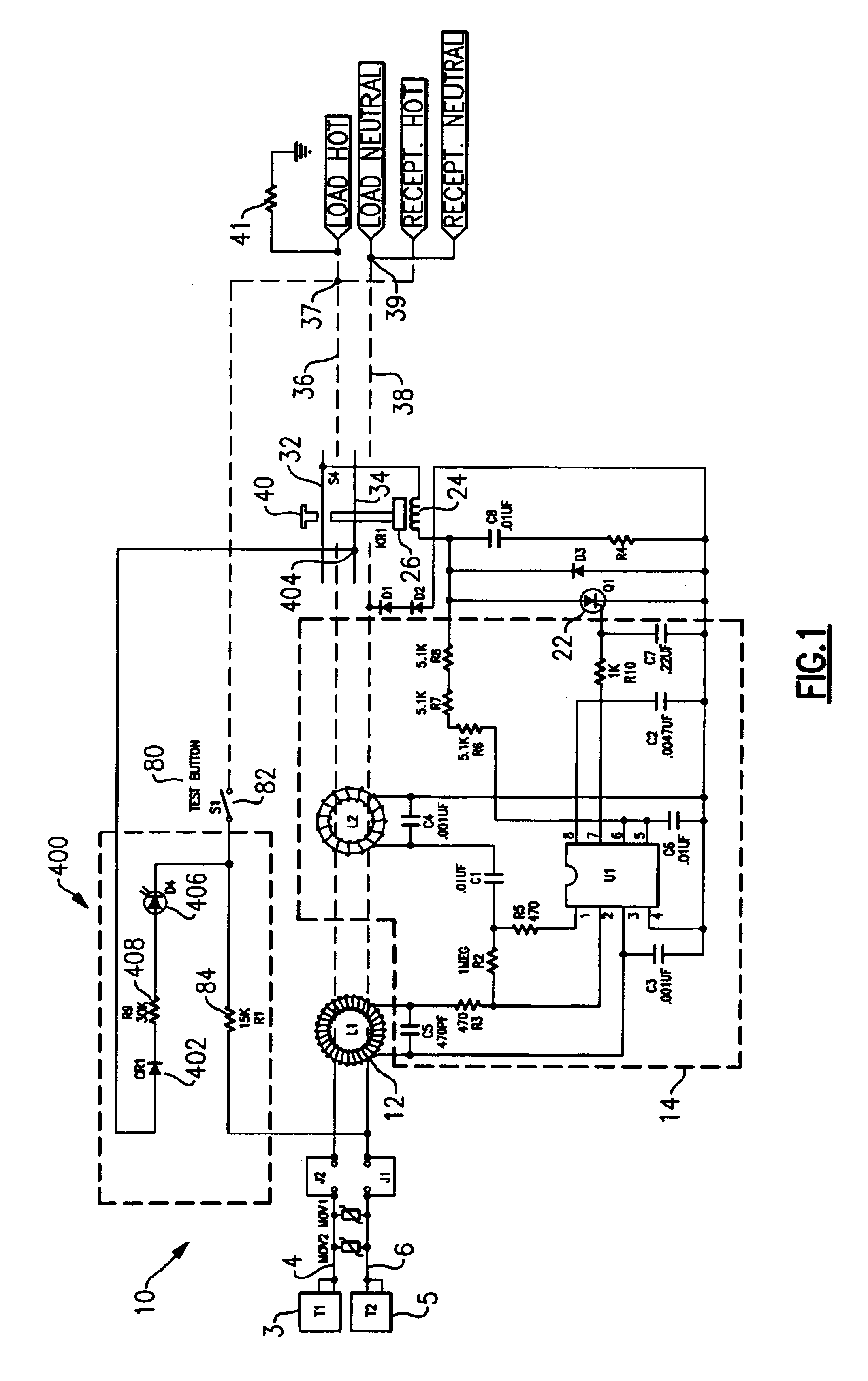
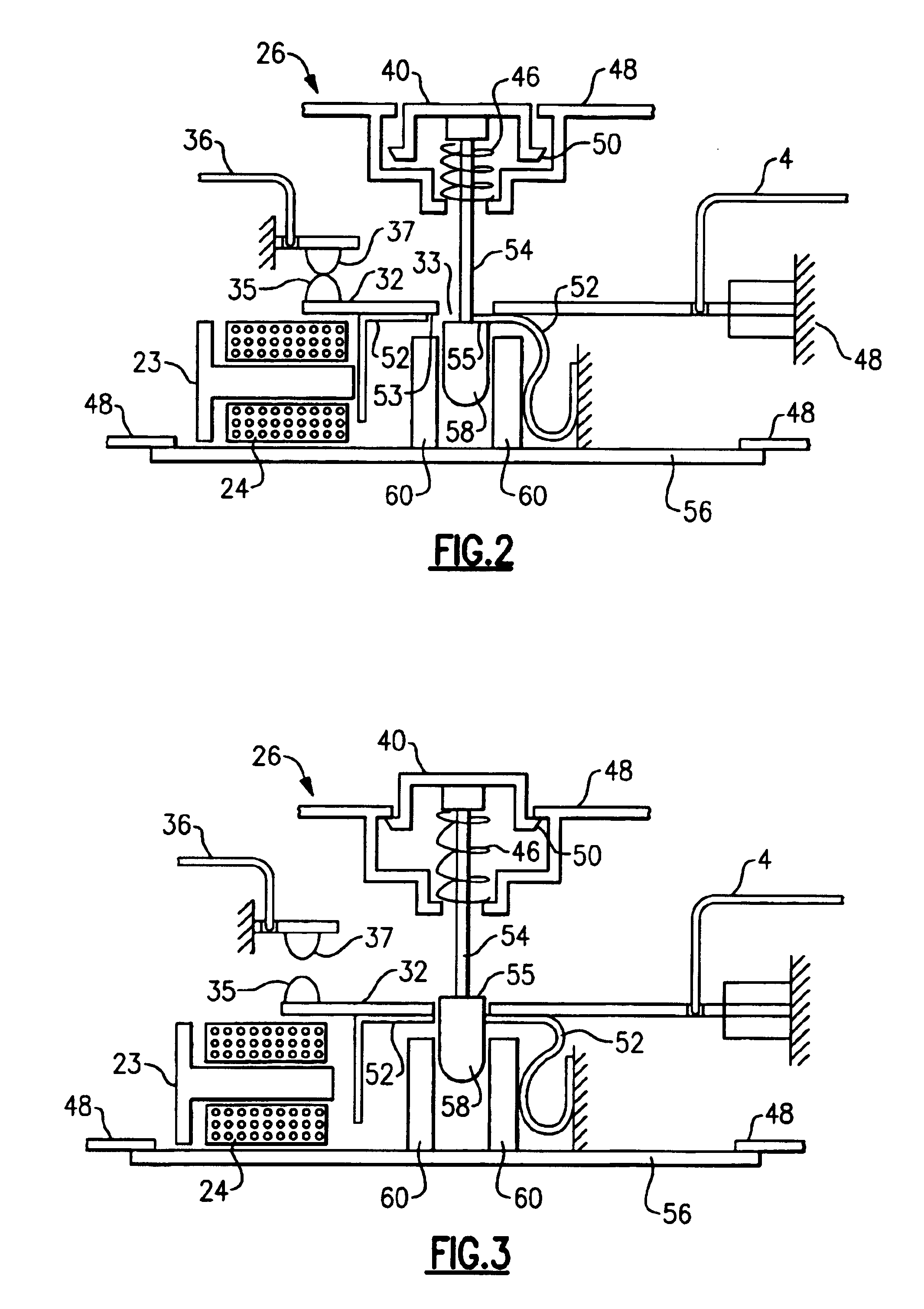
[0011]The present invention addresses the aforementioned needs by providing a protective device that includes an end-of-life indicator. The end-of-life indicator of the present invention is enabled when the trip mechanism fails to cause the circuit interrupter to remove power from the load side within a predetermined time interval after a test has been conducted. The present invention thus provides a user with an end-of-life alarm that communicates to the user that one or more components in the device have reached the end of their operational life.

Problems solved by technology

In the absence of a GFCI, a life threatening electric shock hazard may be present.
A parallel arc fault may be caused by damaged insulation, such as from an overdriven staple.
A series arc fault may be caused by a break in the line or neutral conductors of the electrical distribution system, or may be at a loose terminal at a wiring device within the system.
The current through this type of fault is limited by the impedance of the load.
Since the fault is in series with the load, this type of fault is referred to as a “series arc fault.” In the absence of an AFCI, the current generated by the arc fault may ignite combustible materials and result in fire.
Component failure may occur for a variety of reasons.
For example, failure may occur because of the normal aging of electronic components.
Mechanical parts may become corroded, or experience mechanical wear.
Devices may fail because of mechanical abuse, or because they are overloaded when installed.
Electrical power surges, such as from lightning, also may result in failure.
The sensor, the detector, the switch, trip mechanism, and / or power supply may fail.
As a result, the circuit interrupter may not function to remove power from the load during a fault condition.
Unfortunately, the above approach does not provide the user with any indication that the device is at the end of its useful life.

Method used


Image

  • Protective device with end of life indicator
  • Protective device with end of life indicator
  • Protective device with end of life indicator

Examples


second embodiment

[0044]As embodied herein and depicted in FIG. 4, a schematic of a GFCI device 10 according to the present invention is disclosed. In this embodiment, end-of-life indicator 406 is coupled to a node 512 on an armature 32 or load side conductor 36 (not shown.) Indicator 406 is in series with SCR 510. SCR 510 is coupled to a DC voltage source provided by diode 502, resistor 504, capacitor 506 and Zener 508. Resistor 501 is coupled to contact 82 and to the gate of SCR 510. When contact 82 is closed, a difference current flows through resistor 84 as described above, and a current flows through resistor 501. The current flowing through resistor 501 produces little, or preferably no, difference current between conductors 4 and 6. Thus, any additional current through resistor 501 does not disturb UL's test simulation signal. However, the current flowing through resistor 501 causes SCR 510 to conduct. When SCR 510 conducts, end-of-life indicator 406 is energized. Under normal conditions, end-...

third embodiment

[0046]As embodied herein and depicted in FIG. 5, a schematic of a GFCI device 10 according to the present invention is disclosed. In this embodiment, end-of-life indicator 406 is coupled to transistor 602. Resistor 606 couples contact 82 to the base of transistor 602. When contact 82 is closed, the test difference current is generated, as previously described. When contact 82 is closed, the current through resistor 606 and likewise resistors 604 and 608 produce little, or preferably no difference current between conductors 4 and 6. Thus, the current through resistor 606 does not disturb UL's test simulation signal requirements. On the other hand, current through resistor 606 causes transistor 602 to turn on, to thereby energize end-of-life indicator 406. Again, under normal conditions, end-of-life indicator 406 is energized for approximately 25 milliseconds, as previously described. The indication is thus brief and unnoticeable to the user.

[0047]When device 10 fails, the current thr...

fourth embodiment

[0052]As embodied herein and depicted in FIG. 9, a schematic of a GFCI device 10 according to the present invention is disclosed. In this embodiment, end-of-life indicator 406 is in series with resistor 84 which is coupled to contact 82. The voltage drop of the end-of-life indicator 406 is configured to be less than approximately 10 Volts. Since the current through resistor 84 is typically derived from at least a 120 VAC source, the voltage drop has less than a 10% effect on the current through resistor 84. Thus, the UL requirement for the amount of simulation current are met. Diode 702 can be included in order to achieve a low voltage drop, or to protect end-of-life indicator 406 when the voltage from the electrical power distribution system has a reverse biasing polarity.


PUM


Abstract

The present invention is directed to a protective device that includes a plurality of line terminals configured to be connected to an electrical distribution system, and a plurality of load terminals configured to be connected to a load. The device includes a fault detection circuit coupled to the plurality of line terminals and the plurality of load terminals. The fault detection circuit is configured to detect at least one fault in the electrical distribution system. A power interruption circuit couples the plurality of line terminals to the plurality of load terminals to thereby provide power to the load under normal operating conditions. The power interruption circuit also is coupled to the fault detection circuit, and configured to decouple the plurality of line terminals from the plurality of load terminals in response to the fault detection circuit detecting the at least one fault. A test circuit is coupled to the fault detection circuit and the power interruption circuit. The test circuit is configured to provide a simulated fault signal to the fault detection circuit in response to a user stimulus. An end-of-life indication circuit is coupled to the test circuit and the power interruption circuit. The end-of-life indication circuit provides the user with an end-of-life alarm indicator if the fault detection circuit fails to respond to the simulated fault signal within a predetermined period of time.

Description

CROSS-REFERENCE TO RELATED APPLICATIONS[0001]This is a continuation-in-part of U.S. patent application Ser. No. 10 / 263,028 filed Oct. 2, 2002, the content of which is relied upon and incorporated herein by reference in its entirety, and the benefit of priority under 35 U.S.C. §120 is hereby claimed.BACKGROUND OF THE INVENTION[0002]1. Field of the Invention[0003]The present invention relates generally to devices for protecting electrical circuits, and particularly to devices for protecting electrical circuits having test indicators.[0004]2. Technical Background[0005]An electrical distribution system typically includes a circuit breaker, branch circuit conductors connected to the circuit breaker, and wiring devices connected to the circuit conductors. Wiring devices include receptacles, switches, and other such devices. Each wiring device includes line contacts that couple the device to the source of electrical power, and load contacts that provide power to a load, such as an applianc...

Claims


Application Information

Patent Timeline
Patent Type & Authority Patents(United States)
IPC IPC(8): H01H83/00H01H71/20H01H83/04H01H71/12H02H3/05H02H3/32H02H3/33
CPCH01H71/20H01H83/04H02H3/05H01H2071/044H01H2083/201H02H3/335H02H3/338
Inventor RADOSAVLJEVIC, DEJANPACKARD, THOMAS
Owner PASS SEYMOUR
Learn More