
Method for controlling an adjustment process of a part

a technology of adjustment process and adjustment process, applied in the direction of dynamo-electric converter control, roof, instruments, etc., can solve the problems of tripping of pin protection, complicated process, limited method,

Inactive Publication Date: 2005-10-04
ROBERT BOSCH GMBH
View PDF12 Cites 28 Cited by
  • Summary
  • Abstract
  • Description
  • Claims
  • Application Information

AI Technical Summary

Benefits of technology

The invention relates to a method for controlling an adjustment process, specifically for parts that are moved by a motor drive mechanism. The method aims to prevent pinching or injury caused by the movement of parts during the startup phase of the motor. The method uses a sensor, such as a Hall sensor, to measure the movement of the parts and a pre-calculated limit value to determine when the parts are close to their maximum movement. By triggering the motor at lower power and controlling the rpm, the method prevents overswings in the motor and ensures safe adjustment without excessive force. The method can be used in various adjusting systems without major effort or expense.

Problems solved by technology

It is especially problematic to achieve the pinch protection in the motor startup phase, since overswings in the motor rpm occur then, causing the pinch protection to be tripped by mistake.
The overswinging is caused because the rpm first rises very quickly until the system slack is overcome and then suddenly drops once the part begins to move.
This process is quite complex and expensive and is dependent on the preceding adjustment process.
Moreover, this method is limited to using the rpm or speed as a sensor signal for the pinch protection function.

Method used


Image

  • Method for controlling an adjustment process of a part
  • Method for controlling an adjustment process of a part
  • Method for controlling an adjustment process of a part

Examples


Embodiment Construction

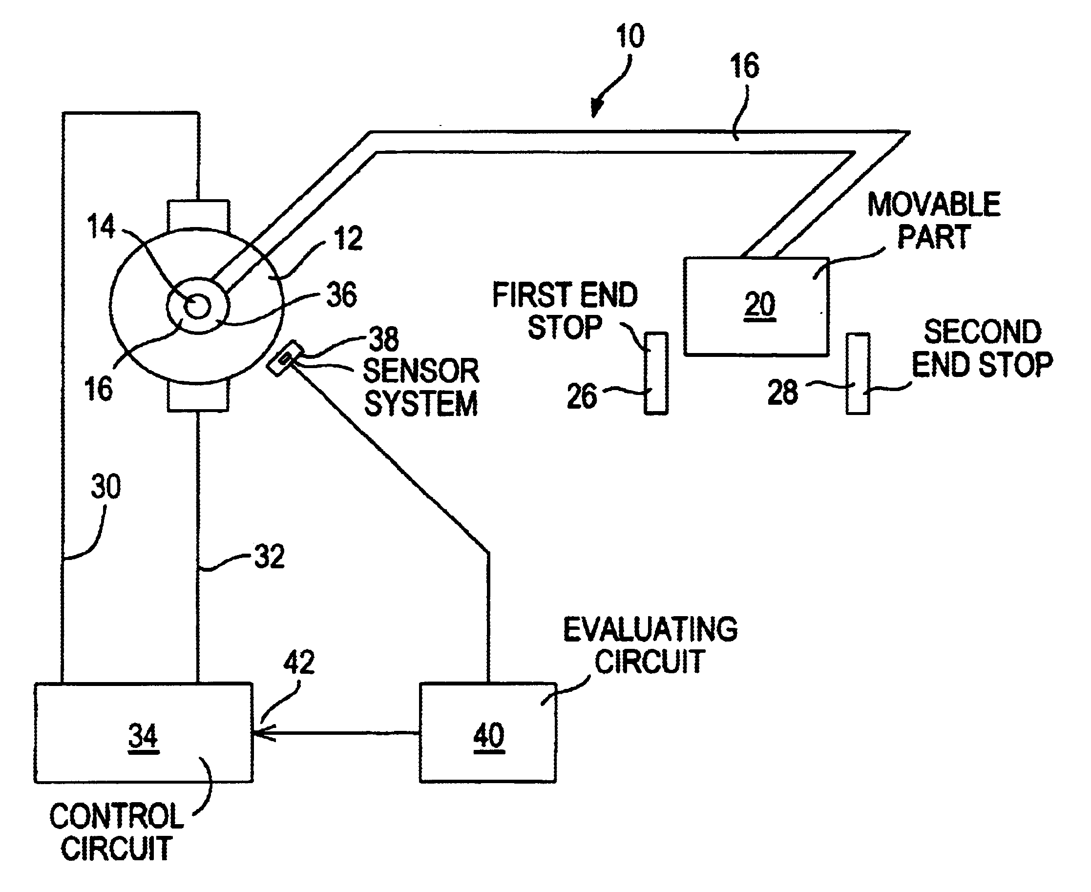
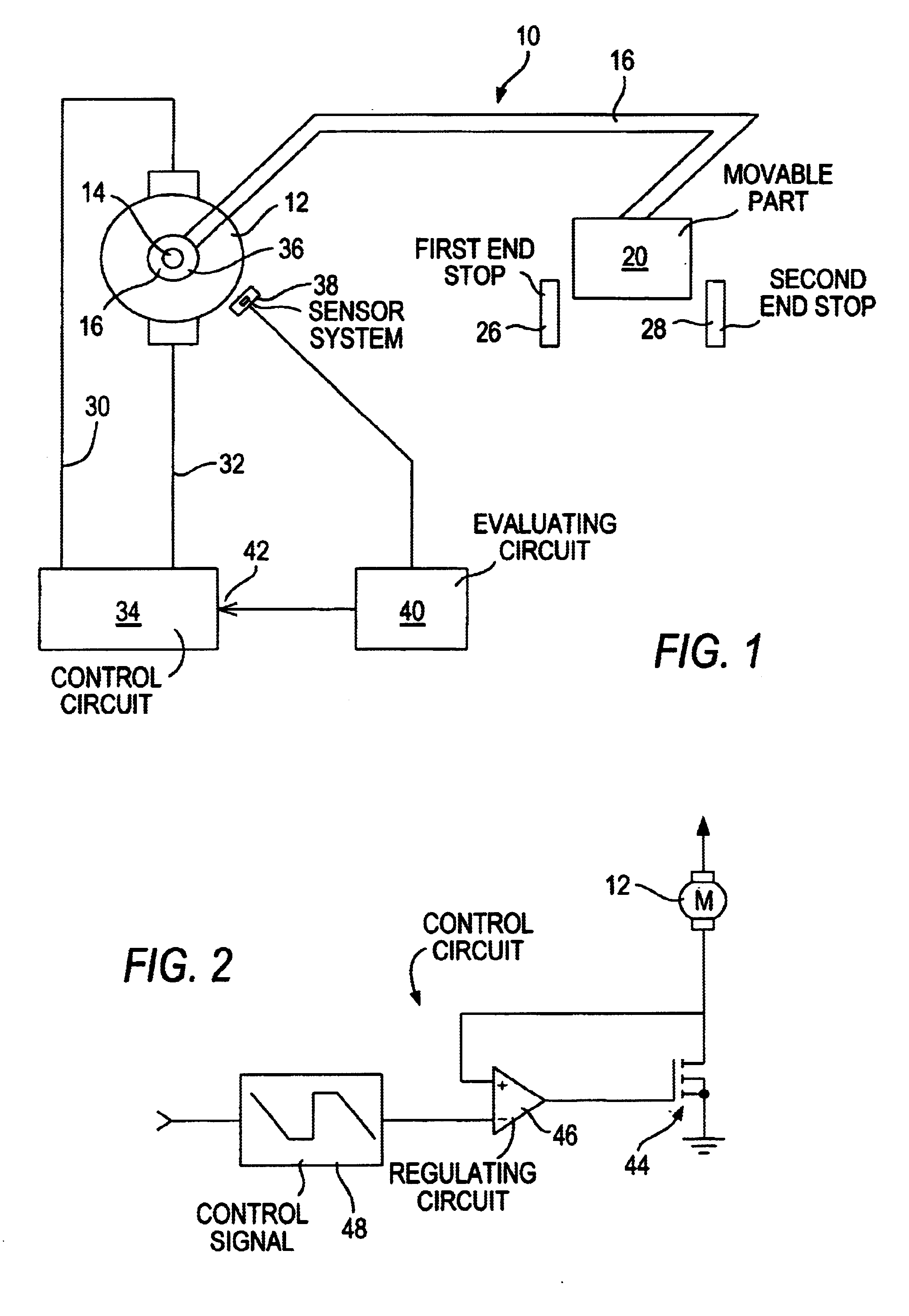
[0024]In FIG. 1, an adjusting system 10 for adjusting a part 20 is shown schematically. The adjusting system 10 has an electric motor 12, with a drive shaft 14 that engages a gear 16 that is merely represented symbolically. The gear 16 is connected via a transmission device 18 to a part 20 to be adjusted. The part 20 can be moved back and forth by means of the electric motor 12 between a first end stop 26 and a second end stop 28. Via motor connection lines 30 and 32, the electric motor 12 is connected to a control circuit 34. The drive shaft 14 of the electric motor 12 carries at least one signal transducer 36, whose signals are detectable by a sensor system 38. The sensor system 38 is connected to an evaluation circuit 40, which in turn is connected to one input 42 of the control circuit 34.

[0025]The adjusting system 10 shown in FIG. 1 can be used for instance in adjusting power windows or power sliding roofs in motor vehicles. However, these are merely two possible uses. It is un...


PUM


Abstract

In the method of controlling a process for moving a part (20) by an electric motor (12) against an end stop, pinching events are detected by monitoring a motor operating variable, such as a motor rpm, and if pinching is detected the motor (12) is stopped and / or reversed. The electric power triggering the motor (12) at the start of and during a startup phase while system slack is taken up is controlled so that it is constant and lower than the power triggering the motor in an ensuing operating phase (54) in which the part (20) moves. Preferably power during the startup phase is reduced to power values that are just barely enough to move the motor while system slack is taken up. In a preferred embodiment the applied motor voltage is reduced and controlled by a power end stage that includes a bipolar transistor or a field effect transistor.

Description

PRIOR ART[0001]The invention relates to a method for controlling an adjustment process as generically defined by the preamble to the main claim.[0002]It is known for parts to be combined with a motor drive mechanism that moves the parts along an adjustment path. The parts can be moved against at least one terminal position, and in particular can be moved back and forth between two terminal positions. Such movable parts are used in motor vehicles, for instance, as power windows or electrically actuated sliding roofs or seat adjusters. Electric closing devices for motor vehicles must by law provide a pinch protection function, which should largely preclude injuries to users from getting body parts caught.[0003]It is especially problematic to achieve the pinch protection in the motor startup phase, since overswings in the motor rpm occur then, causing the pinch protection to be tripped by mistake. The overswinging is caused because the rpm first rises very quickly until the system slac...

Claims


Application Information

Patent Timeline
Patent Type & Authority Patents(United States)
IPC IPC(8): E05F15/00H02H7/085B60J1/00B60J7/057E05F15/41H02H7/093
CPCH02H7/0855E05F15/41H02H7/0851E05Y2900/542E05Y2900/55H02H9/001H02H7/085
Inventor LAMM, HUBERT
Owner ROBERT BOSCH GMBH
Learn More