Eureka AIR delivers breakthrough ideas for toughest innovation challenges, trusted by R&D personnel around the world.

Sectional door system

a sectional door and door body technology, applied in the direction of door/window protective devices, shutters/movable grilles, wing accessories, etc., can solve the problems of entrapment between the sections, troublesome methods, and more difficult hinge inserting

Inactive Publication Date: 2005-10-04
OVERHEAD DOOR
View PDF30 Cites 23 Cited by
  • Summary
  • Abstract
  • Description
  • Claims
  • Application Information

AI Technical Summary

Benefits of technology

[0010]In light of the foregoing, it is an object of the present invention to provide a door panel interface formed integrally in adjacent panels, where the interface bears a portion of the weight of the door and performs a pinch-resisting function. It is another object of the present invention to provide an overhead sectional door having a plurality of panels, each panel having a rearwardly extending interface, where a portion of the weight of a superjacent section is borne by a portion of a subjacent section at the front surface and at an intermediate point of the interface between the front and rear of the panel. Yet another object of the present invention, is to provide a joint surface on the subjacent section carrying a raised portion intermediate of the front plane and rear plane that bears a portion of the weight of the superjacent section and prevents intrusion of foreign objects during articulation of the door sections. Still another object of the present invention, is to provide an overhead sectional door where the joint surfaces of adjacent sections are adapted to pivot with respect to each other through a range of motion as the door is moved from a generally closed vertical position to a generally open horizontal position, where a raised portion of the joint assemblies remains in proximity to the opposite joint surface through a portion of the range of motion to prevent intrusion by foreign objects.
[0011]Another object of the present invention, is to provide a sectional door where the bearing surface of the joint interface is oriented to bear the weight of the door. Still another object of the present invention, is to provide a joint interface having a bearing portion located intermediate of the front and rear faces of a door section. Yet another object of the present invention is to provide a bearing position that facilitates pivotal movement between adjacent door sections. It is still another object of the present invention to provide a raised bearing portion on a joint surface in the interface that contacts an opposite joint surface where the raised portion slopes downward toward the rear of the door section.
[0012]Another object of the present invention is to provide a sectional door that carries the door rollers independently of the hinges between adjacent panels. A further object of the present invention is to provide a roller receiver formed in a door section adjacent to the joint interface. Still a further object of the present invention, is to provide a roller carrier located between the front and rear surfaces of a door section which takes up less interior space when the door is closed and provides more headroom when the door is open and minimizes back break between the top panel and its adjacent panel in the open, horizontal position. Yet another object of the present invention is to provide an end stile inserted within the contours of a door section providing additional support thereto, where the roller carrier is carried by the end stile. Still another object of the present invention is to provide a carrier block insertably received within the end stile, where the carrier block holds the roller and may be non-metallic to reduce noise.
[0013]Another object of the present invention is to provide a door system that can be packaged for shipment where the track system and drive tube fit within the door sections, thereby requiring no additional room for shipping and reducing the instance of lost components. A further object of the present invention is to provide component receivers formed on the door sections to stow components including the track system and drive tube for packaging and shipping purposes. Still a further object of the present invention is to provide such component receivers formed in the stiles of a door section.
[0014]Another object of the present invention is to provide an overhead sectional door having a single leaf hinge joining adjacent sections. A further object of the present invention is to provide a single leaf hinge that may be attached to a door section before the sections are joined together. Yet another object of the present invention is to provide a single leaf hinge that allows the hinge leaf to remain attached to a first section in a position outside the normal movement of the hinge during operation until such time as the installer desires to attach the leaf to the second section. A further object of the invention is to provide such a single leaf hinge having a curl which interfits with a panel stile at one end and attaches by fasteners to the stile of an adjacent panel of a door for quick, easy installation.
[0015]Another object of the present invention is to provide an overhead sectional door having a cable attachment assembly at the bottom of the door that serves as a roller carrier for the bottom roller. Still another object of the present invention is to provide a cable attachment assembly that includes a bore adapted to receive the shaft of a roller constituting the bottom roller of the door, thereby eliminating a bottom bracket and fasteners.

Problems solved by technology

Attendant to the pivoting of door sections is the risk of entrapment between those sections, which has led to the development of a number of pinch-resistant designs.
Unfortunately, manufacturing tolerances and variances make this method troublesome.
While this improves the panel spacing in the interface area, as the panels get larger and heavier it becomes more difficult to insert the hinges.
In either of the above-described designs, the roller location must remain constant to the lower panel or undesired movement of the panels through the transitional radius will occur.
These packages that are separate from the panel packages are different in size leaving undesirable voids in the shipping container as well as the possibility of missing components, when the door components are delivered to the job site.
Unfortunately, the components needed to be separated at the shipment termination requiring additional time to prepare the door for installation.
Further, this did not relieve the possibility of components being lost during shipment and additional handling of components.
While reducing the number of lost parts, handling and storage or stowage become a significantly greater burden.

Method used


Image

  • Sectional door system
  • Sectional door system
  • Sectional door system

Examples


Embodiment Construction

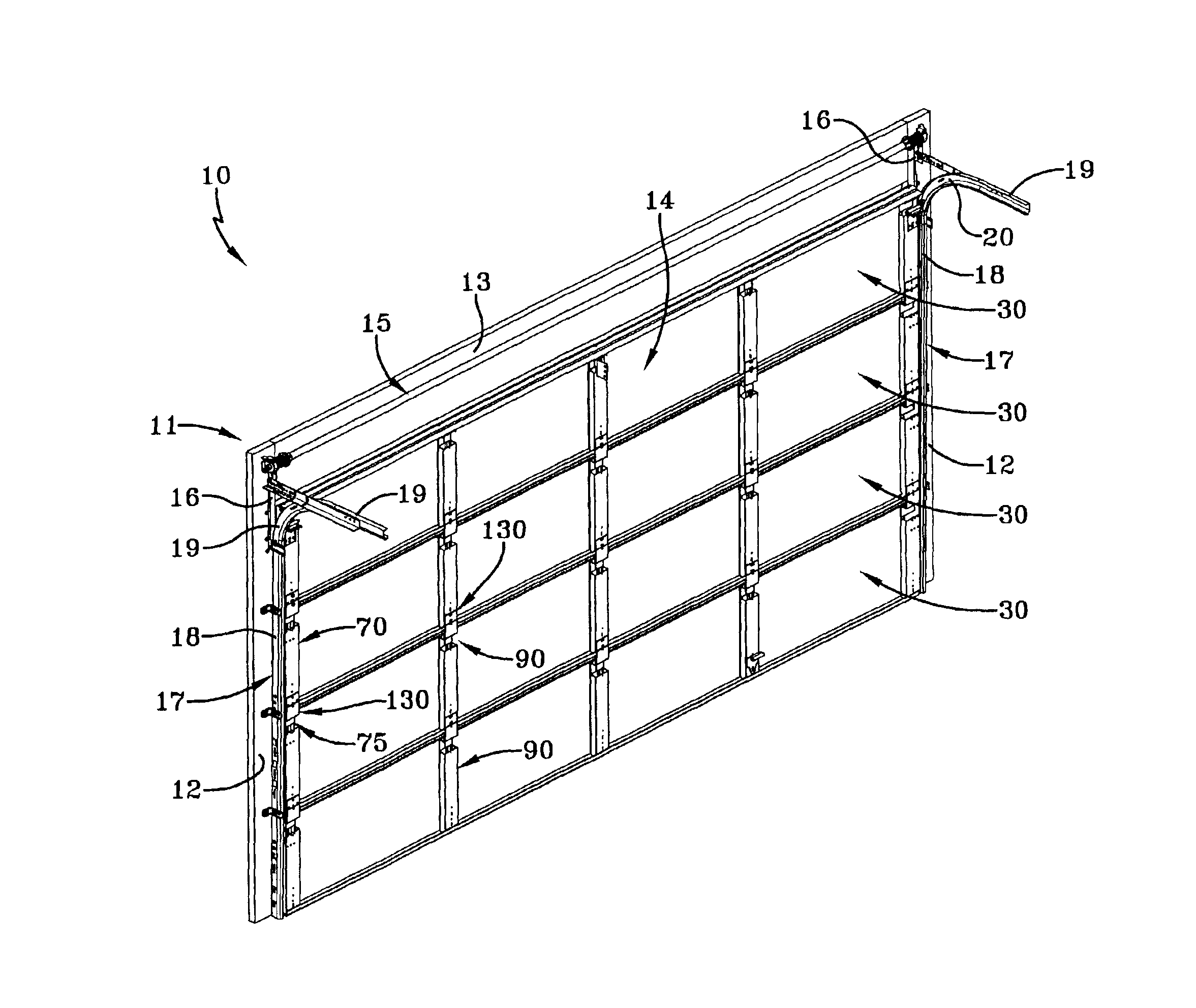
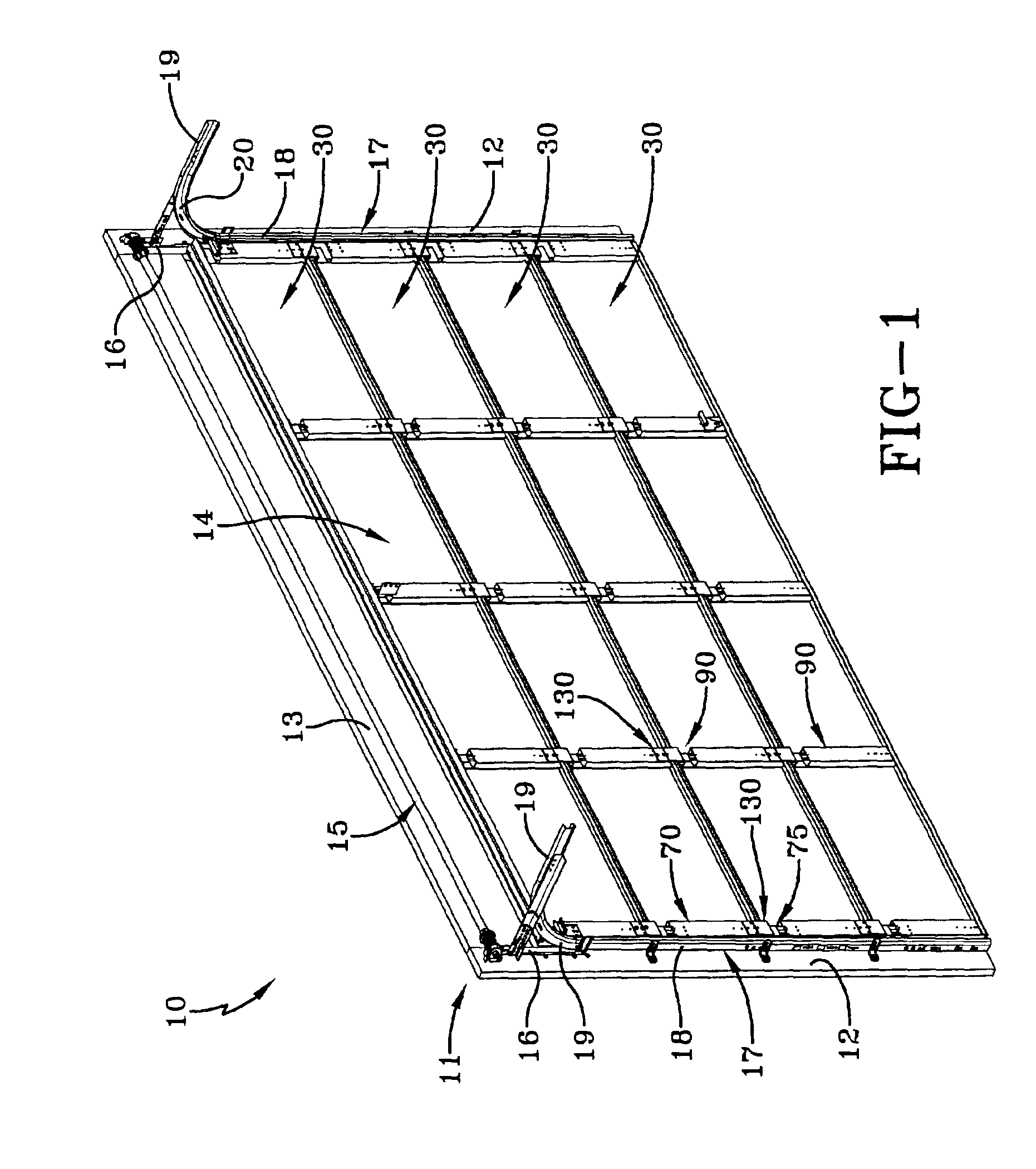
[0028]An upward acting insulated or uninsulated sectional door system embodying the concepts of present invention is generally indicated by the numeral 10 in FIG. 1 of the drawings. The door system 10 is positioned and mounted for opening and closing movement in a building, trailer or other structure by a peripheral door frame, generally indicated by the numeral 11. The frame 11 consists of a pair of spaced vertical jambs 12, that, as seen in FIG. 1, are generally parallel and extend vertically upwardly relative to a supporting surface such as the ground, a floor, or the bed of a trailer (not shown). The vertical jambs 12, 12 are spaced and joined proximate their vertical upper extremity as by a header 13 to thereby define the generally inverted U-shaped frame 11 for mounting a door, generally indicated by the numeral 14. The frame 11 may be constructed of wood, metal, or other relatively high-strength, rigid material for purposes of reinforcement, attachment to a building or vehicl...


PUM


Abstract

A sectional door including, a plurality of panels pivotally joined to each other, the panels including a facer having a front surface, a first joint member and a second joint member extending rearwardly of the facer, a pair of end stiles received at lateral extremities of the panels and placed in supporting relation thereto, the stiles having a recess adjacent one of the joint member, a hinge receiver located adjacent the recess and a hinge pivotally coupled to one of the panels at the hinge receiver and fastened to another of the panels at the end stile, wherein the recess provides a clearance for pivoting movement of the hinge and the storage or stowage of door components.

Description

TECHNICAL FIELD[0001]The present invention relates generally to upward acting sectional door systems. More particularly, the present invention relates to an insulated or noninsulated sectional door having a single leaf hinge and a pinch-resistant section to section interface of the door panels. The track system and counterbalance system drive tube for the door system are receivable within the door sections, thereby requiring no additional space for shipping.BACKGROUND ART[0002]Upwardly acting sectional doors have become commonplace in a variety of applications including buildings, trucks, and trailers. These doors are characterized by a plurality of hinged sections or panels that articulate in a pivoting fashion as the door is moved from a generally vertical, closed position to a horizontal, open position. Attendant to the pivoting of door sections is the risk of entrapment between those sections, which has led to the development of a number of pinch-resistant designs. Such doors ar...

Claims


Application Information

Patent Timeline
Patent Type & Authority Patents(United States)
IPC IPC(8): E05D15/24E05D15/16E06B3/32E06B3/48
CPCE05D15/24E05D15/242E06B3/485E05Y2900/106
Inventor MULLET, WILLIS J.
Owner OVERHEAD DOOR
Why Eureka
Eureka Blog
Learn More