
Method and apparatus for making thin brick wall facing

a technology of thin bricks and facings, which is applied in the direction of building components, covering/linings, building repairs, etc., can solve the problems of not being able to optimize the drainage of moisture or water behind the thin bricks, time-consuming, labor-intensive, and thus expensive, and achieves better water management, more economical and reliable effects

Inactive Publication Date: 2005-10-04
PASSENO JAMES KENNETH
View PDF14 Cites 45 Cited by
  • Summary
  • Abstract
  • Description
  • Claims
  • Application Information

AI Technical Summary

Benefits of technology

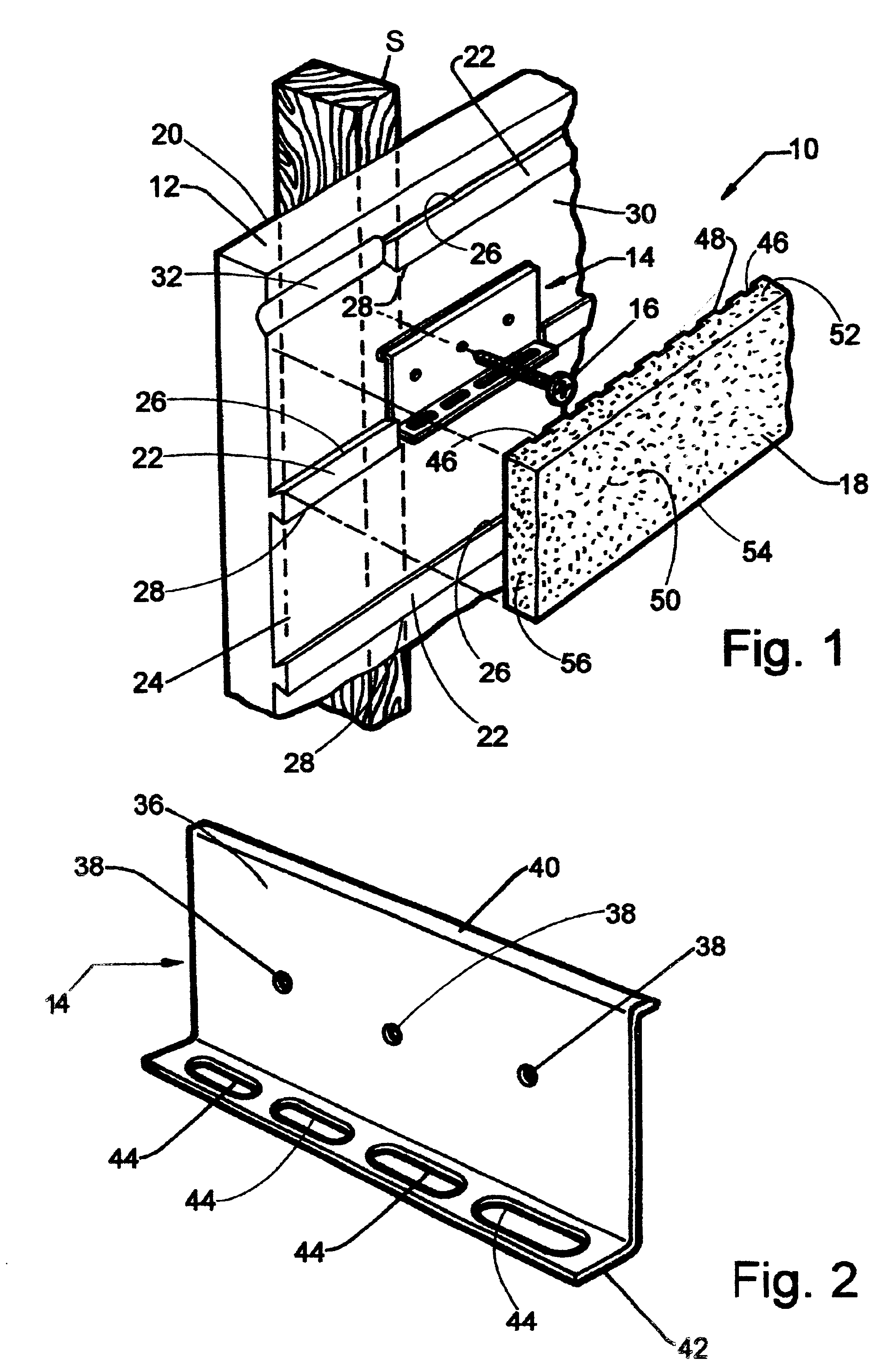
[0018]The thin bricks each have a front surface, a back surface, a top surface, a bottom surface, and opposed side surfaces. Each brick has a width defined between the opposed side surfaces, a height defined between the top and bottom surfaces, and a depth defined between the front and back surfaces. The back surface of the thin bricks includes vertical weeping grooves that improve water migration by channeling water that would otherwise become trapped between the bricks and the substratum.
[0021]The interruptions work in conjunction with the weeping grooves to channel out water from behind the bricks. The excessive horizontal distance between the drainage grooves of the prior art restricts moisture migration, and typically only the water in the vicinity of the groove is channeled out. The spacing and arrangement of the interruptions in the preferred embodiment greatly reduces the horizontal distance between interruptions such that the channeling system is accessible to any water behind the thin bricks.
[0027]It is another object to provide a brick panel assembly and related method that, compared to the prior art, provides better water management by more completely permitting moisture to drain therefrom.
[0028]It is still another object to provide a brick panel assembly and related method that is more economical and more reliable than the prior art.
[0030]It is a further object to provide a brick panel assembly and related method that provides improved mortar interlock and brick retention compared to the prior art.

Problems solved by technology

Unfortunately, brick walls are typically laid brick by brick, which tends to be time consuming, labor intensive, and thus expensive.
A disadvantage with these teachings is that it is not optimized to drain moisture or water from behind the thin bricks.
Unfortunately, the manufacturing of the substratum is somewhat complex in that it involves vacuum forming a thin polystyrene sheet and laminating that sheet to the rigid polystyrene foam backing member.
A disadvantage with the Francis et al. patents, however, is that some of the thin bricks attach to the flat plate portion of a support clip and rest on the tops of the shelf portions of the support clips, while others do not.
Furthermore, the bricks resting on the flat plate portion of a support clip are vertically higher than the bricks attached directly to the backing member giving rise to uneven rows of thin bricks.
Another disadvantage with the Francis et al. patents is that the thin vertical notches only permit a relatively small amount of water to escape from under the mortar, and only in vertically spaced apart portions of the panel assembly.
Additionally, and as shown in the cross-section of FIG. 3 of the Francis et al. patents, the interlocking rows of teeth of the support clips lie just below the surface of the mortar, which is insufficiently shallow to optimally finish the retaining grout, and results in the teeth showing after a finish trowel is passed down the mortar or grout groove.
Thus, the thin bricks are not optimally retained to the backing member and may fall off the wall after assembly.
From the above, it can be appreciated that thin brick panel assemblies of the prior art are not cost effectively optimized to manage drainage of water from under the mortar and to provide a robust integral engagement of the thin bricks to the substratum.

Method used


Image

  • Method and apparatus for making thin brick wall facing
  • Method and apparatus for making thin brick wall facing
  • Method and apparatus for making thin brick wall facing

Examples


Embodiment Construction

[0040]Generally shown in the Figures, a thin brick panel assembly is provided in accordance with the present invention. The term substratum as used herein is synonymous with backing member and means any member or element that constitutes a base for supporting another member or element.

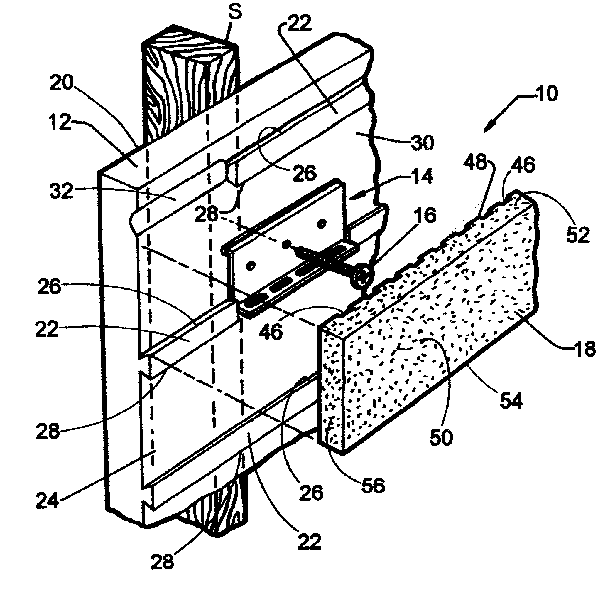
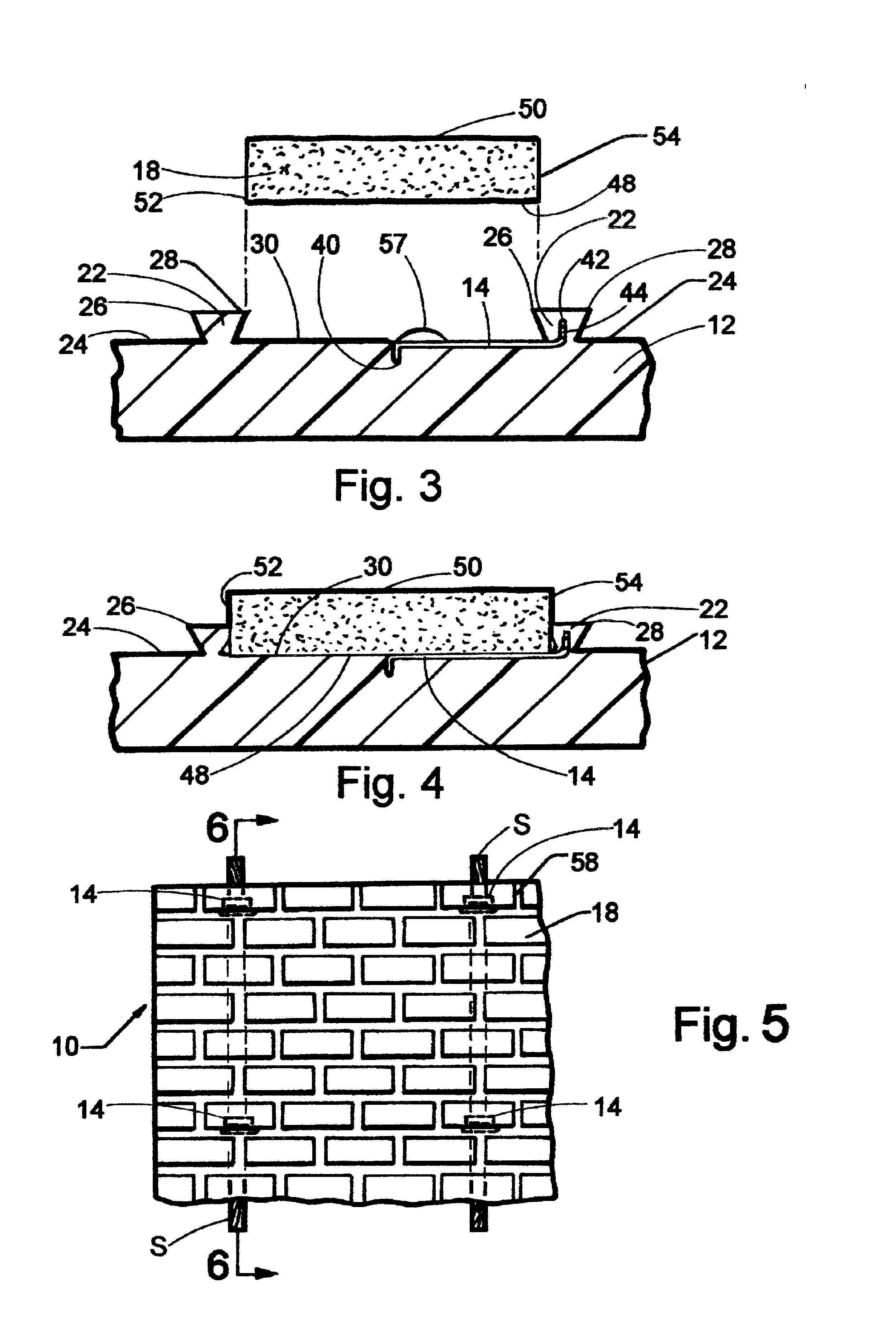
[0041]Referring now to the Figures, there is shown in FIG. 1 a portion of a thin brick panel assembly 10 that is constructed in accordance with the present invention. The thin brick panel assembly 10 includes a substratum 12, mortar ties 14, fasteners 16, bricks 18 and mortar 58 (see FIG. 6). The thin brick panel assembly 10 is shown attached to a wall stud S of a building structure. The substratum 12 is prefastened between adjacent wall studs S by applying a bead of construction adhesive (not shown) down the wall studs S, pressing a back surface 20 of the substratum 12 to the wall studs S, and then leveling the substratum 12 thereto before the construction adhesive sets. The substratum 12 is further a...


PUM


Abstract

A thin brick panel assembly having improved water drainage and integral brick retention. A substratum includes horizontal rows of dovetail-shaped projections with interruptions therein. Mortar ties having a flat plate portion, a substratum engagement extension, and mortar engagement extension are fastened to the substratum such that the mortar engagement extensions align with the interruptions in the projections. Bricks are snap-fit to the substratum over the mortar ties and between the projections. The bricks crush portions of the dovetail-shaped projections and lie flat against the mortar ties. Mortar is applied between the bricks and flows through apertures in the mortar engagement extensions of the mortar ties to interlock the mortar ties, the substratum and the bricks.

Description

CROSS-REFERENCES TO RELATED APPLICATIONS[0001]Not applicable.FEDERALLY SPONSORED RESEARCH OR DEVELOPMENT[0002]Not applicable.REFERENCE TO A MICROFICHE APPENDIX[0003]Not applicable.BACKGROUND OF THE INVENTION[0004]1. Field of the Invention[0005]The present invention generally relates to brick panel wall construction. More specifically, this invention is directed to improvements in the components used in brick panel wall construction that result in improved water management, stronger mortar interlock, and better brick retention.[0006]2. Description of the Related Art[0007]For centuries brick walls have been used as a premium building material due to their strength, beauty, and durability. Unfortunately, brick walls are typically laid brick by brick, which tends to be time consuming, labor intensive, and thus expensive. Thin brick veneer was, therefore, developed as a means for achieving the beauty and durability of brick walls without the associated expense.[0008]Thin brick panels can...

Claims


Application Information

Patent Timeline
IPC IPC(8): E04F13/08
CPCE04F13/0862
Inventor PASSENO, JAMES KENNETH
Owner PASSENO JAMES KENNETH
Learn More