
Technique for conveying overload conditions from an AC adapter to a load powered by the adapter

a technology of overload conditions and ac adapters, which is applied in the direction of instruments, liquid/fluent solid measurement, transportation and packaging, etc., can solve the problems of reducing the output voltage of the primary circuit, and achieve the effect of reducing power draw, reducing or even ceasing the charge current to the battery, and reducing the charge curren

Inactive Publication Date: 2005-09-27
HEWLETT PACKARD DEV CO LP
View PDF6 Cites 149 Cited by
  • Summary
  • Abstract
  • Description
  • Claims
  • Application Information

AI Technical Summary

Benefits of technology

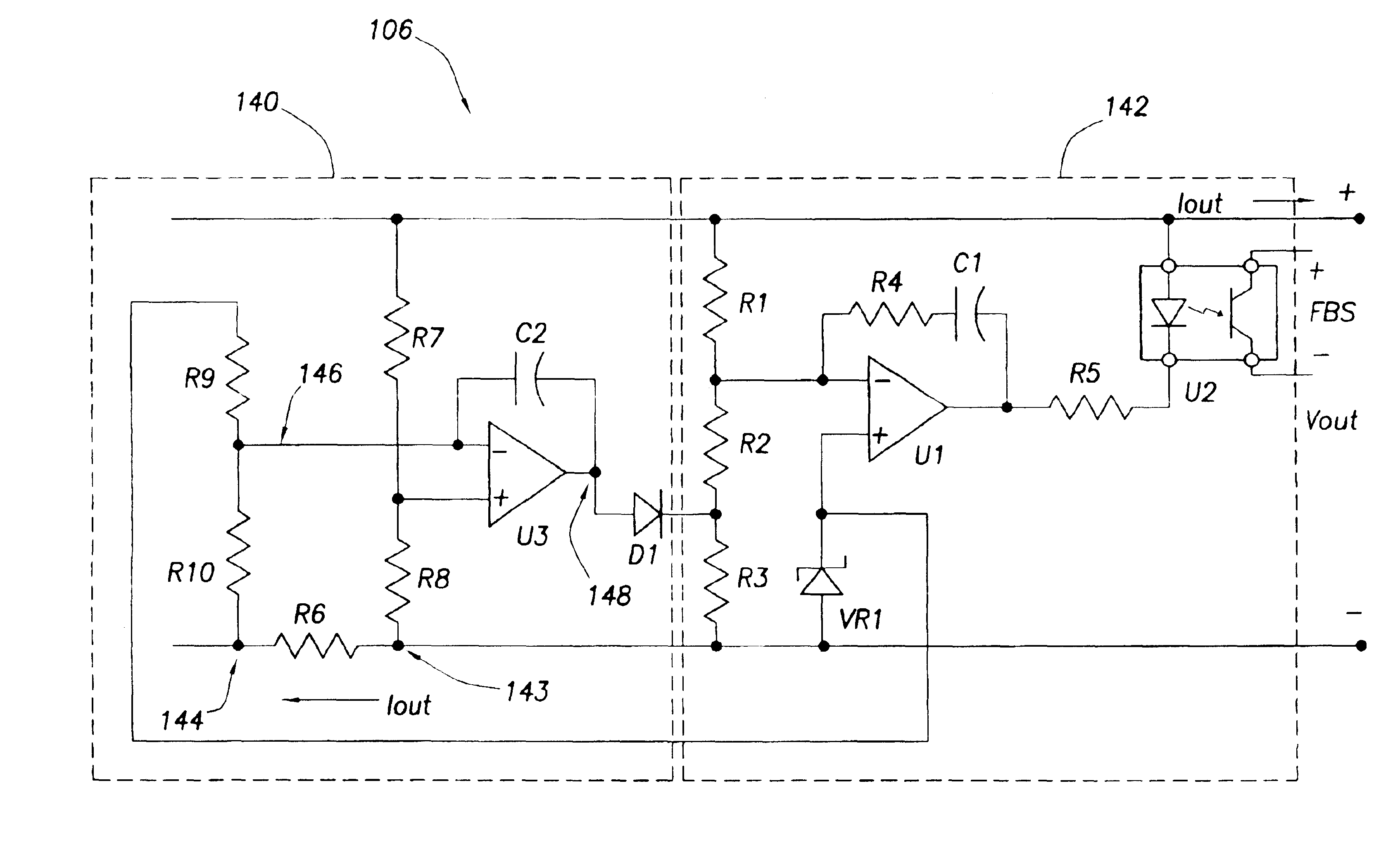
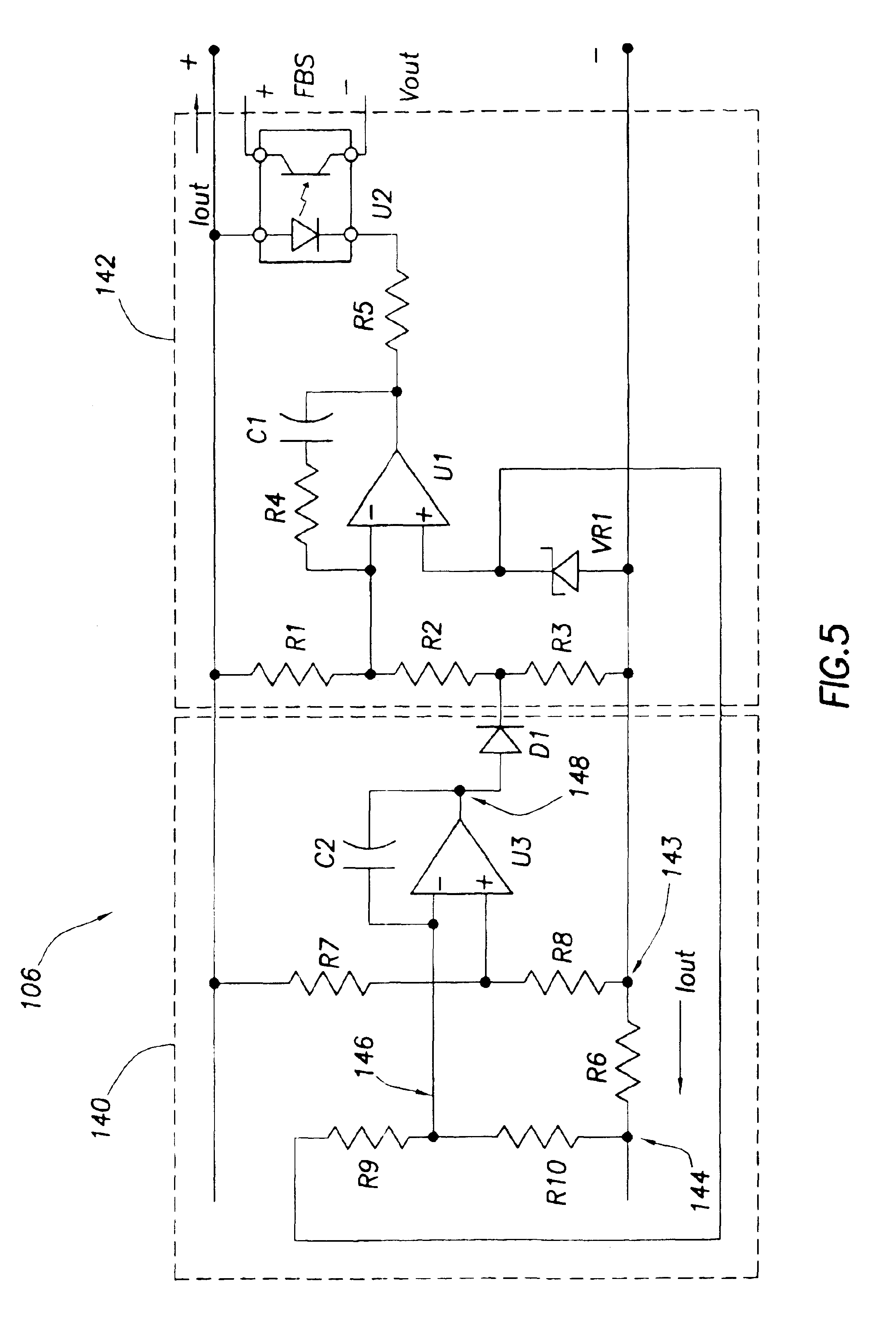
[0017]One or more loads that draw power from the adapter may be adapted to detect a drop in the AC adapter's output voltage. When such a voltage drop is detected, that information tells the load that too much current is being drawn from the adapter and that the load should throttle back to decrease the power draw on the AC adapter. If the load is the battery charger and battery, the charger can throttle back charging by reducing or even ceasing the charge current to the battery. Throttling back charge current results in a lower power draw on the adapter thereby alleviating the excessive power draw condition experienced by the adapter. The load could also be the computer for which the processor could be throttled back by reducing its clock frequency. Alternatively, power could be saved by dimming the display or altering the operation of any other function of the computer.

Problems solved by technology

If output current exceeds a threshold, however, the power regulator provides a signal to the voltage feedback current which, in turn, causes the primary circuit to reduce the output voltage.

Method used


Image

  • Technique for conveying overload conditions from an AC adapter to a load powered by the adapter
  • Technique for conveying overload conditions from an AC adapter to a load powered by the adapter
  • Technique for conveying overload conditions from an AC adapter to a load powered by the adapter

Examples


Embodiment Construction

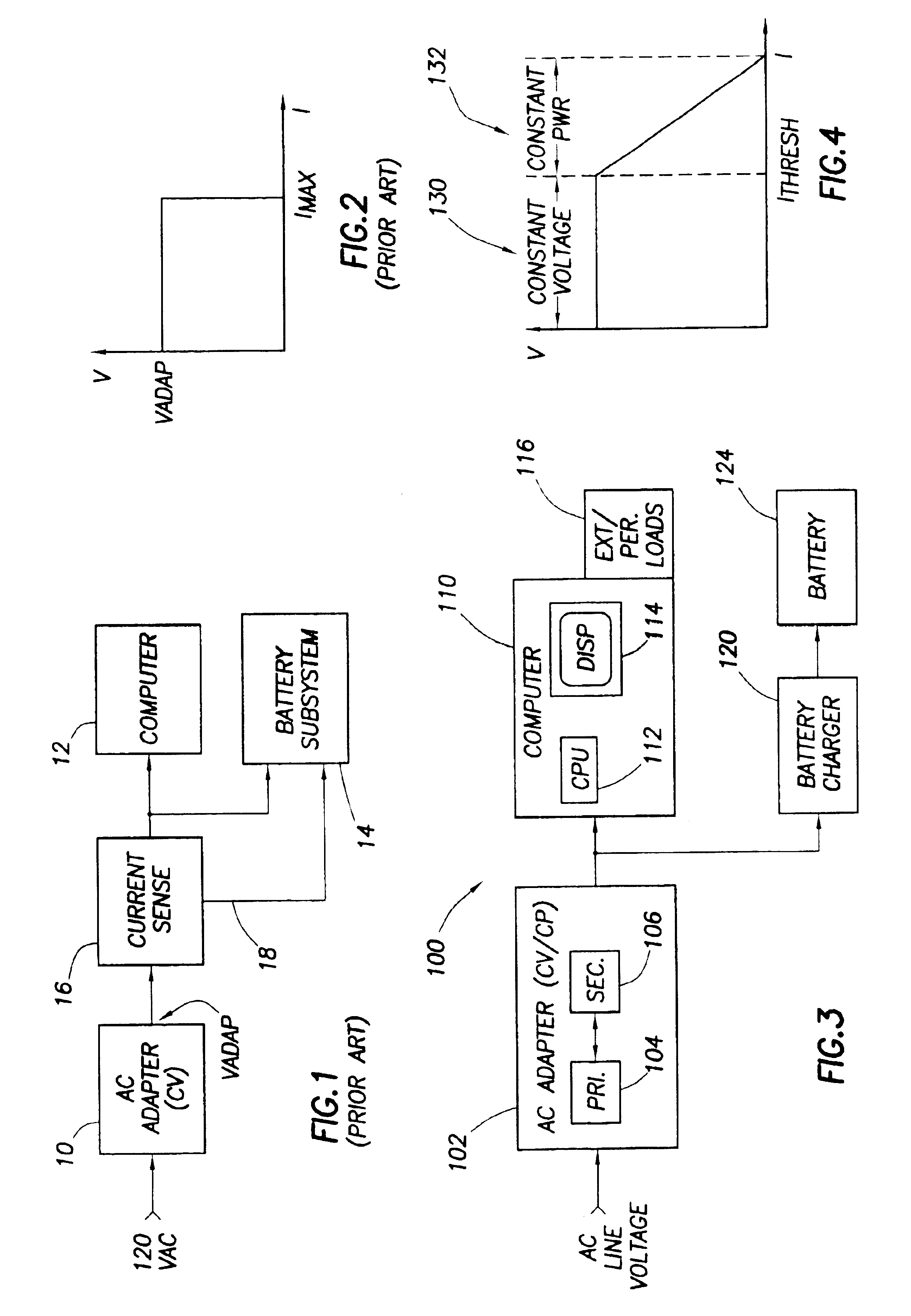
[0030]Referring now to FIG. 3, computer system 100, constructed in accordance with the preferred embodiment of the invention, includes an AC adapter 102, a computer 110, a battery charger 120, and a battery 124. As shown, the AC adapter 102 converts the incoming AC line voltage to a lower DC output voltage (e.g., 18 VDC) and provides the DC power to the computer 110 and the battery charger 120 to operate those subsystems. Other components may be included as desired.

[0031]The computer 110 generally includes one or more CPUs 112, a display (e.g., an LCD display) 114, one or more peripheral or external loads (e.g., PCMCIA cards, modems, CD ROM drive, etc.), and other components known to those of ordinary skill in the art that have been omitted for sake of clarity. For purposes of the preferred embodiment, computer 110 simply represents a load on the AC adapter 102.

[0032]The battery charger 120 represents another load on the adapter 102. In general, the battery charger comprises a DC / DC...


PUM


Abstract

A constant voltage / constant power AC adapter converts AC voltage to DC voltage to provide power to a plurality of loads. The adapter's output characteristic is approximately a constant voltage as long as the output current draw by the loads is less than a threshold (e.g. a safety threshold for the adapter). If, however, the power draw on the adapter is such that the output current exceeds the threshold, the adapter then decreases its output voltage to maintain the power draw at a safe level. One or more loads that draw power from the adapter may be adapted to detect a drop in the AC adapter's output voltage. When such a voltage drop is detected, that information tells the load that too much current is being drawn from the adapter and that the load should throttle back (e.g., reducing battery charge current, CPU clock frequency, display brightness, etc.).

Description

CROSS-REFERENCE TO RELATED APPLICATIONS[0001]Not applicable.STATEMENT REGARDING FEDERALLY SPONSORED RESEARCH OR DEVELOPMENT[0002]Not applicable.BACKGROUND OF THE INVENTION[0003]1. Field of the Invention[0004]The present invention generally relates to a battery-powered electronic device. More particularly, the invention relates to a technique for providing power to components in an electronic device in such a way that the devices can determine when an overload condition is occurring.[0005]2. Background of the Invention[0006]Most every computer system with a rechargeable battery uses an external AC to DC converter (sometimes called an “adapter”) which converts the AC line voltage to a lower DC voltage. An example is shown in FIG. 1 in which an AC adapter 10 provides power for a computer 12 and a battery subsystem 14. The battery subsystem includes a battery charger and a battery. The current sense circuit 16 will be discussed below.[0007]Due to its size and shape, the adapter has ofte...

Claims


Application Information

Patent Timeline
Patent Type & Authority Patents(United States)
IPC IPC(8): G06F1/30H02J7/00H02J7/34
CPCG06F1/30H02J7/0068H02J7/34
Inventor SAWYERS, THOMAS P.KOK, JAMES MUN WAI
Owner HEWLETT PACKARD DEV CO LP
Learn More