Wireless receiving apparatus and method

a wireless receiving and wireless technology, applied in the field of wireless receiving, can solve the problems of inability the complexity of the wireless receiver b>1/b>, and the disadvantage of the prior art, so as to reduce the size of the wireless receiving apparatus, simplify the circuitry, and reduce the number of mcus

Inactive Publication Date: 2005-09-27
GLOBALINK TECH
View PDF5 Cites 6 Cited by
  • Summary
  • Abstract
  • Description
  • Claims
  • Application Information

AI Technical Summary

Benefits of technology

[0004]It is therefore an object of the present invention to provide a wireless receiving apparatus comprising a single MCU (microprocessor control unit) which is capable of both receiving and processing signals having different frequencies transmitted from a plurality of peripheral devices simultaneously. By utilizing this apparatus, it is possible to synchronously receive signals so as to decrease the number of MCUs, simplify the circuitry, and reduce the size of the wireless receiving apparatus.

Problems solved by technology

However, the prior art suffered from a disadvantage.
This inevitably makes the wireless receiver 1 much too complicated, making a reduction in size impossible.

Method used


Image

  • Wireless receiving apparatus and method
  • Wireless receiving apparatus and method
  • Wireless receiving apparatus and method

Examples


first embodiment

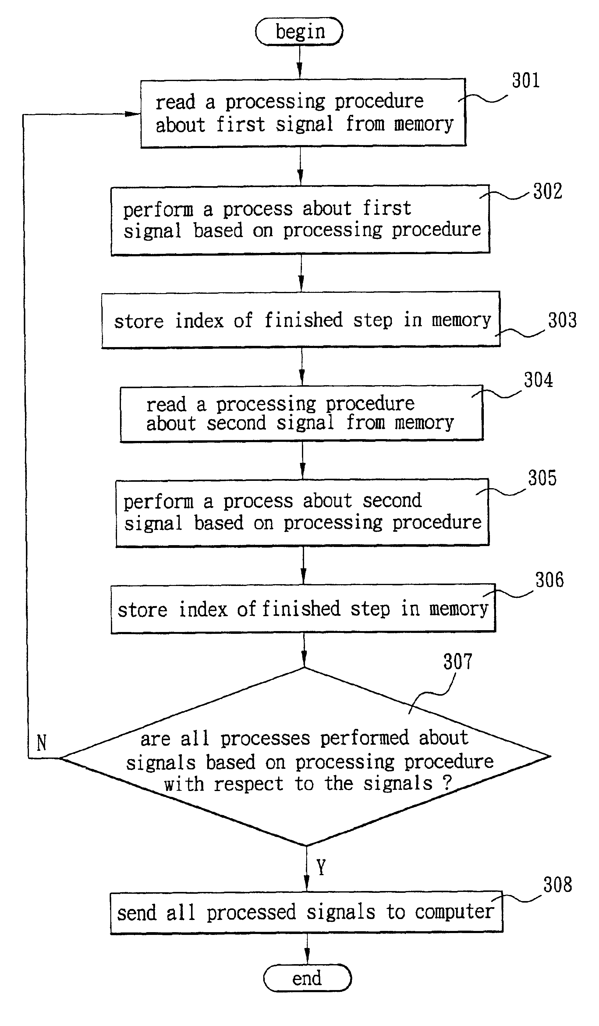
[0025]Referring to FIG. 4, there is shown a flow chart illustrating a process according to the invention. After MCU 23 has finished an identification, a process is performed with respect to the signal having the first frequency transmitted from signal receiving circuit 21 in a multi-segment multi-task data processing mode. The steps of the process are as follows:

[0026]In step 401, after signal having first frequency transmitted from signal receiving circuit 21 has been received, read a signal conversion table stored in memory 25.

[0027]In step 402, a determination is made whether a type of the received signal has a corresponding type of signal in conversion table. If yes, process goes to step 403. Otherwise, process loops back to step 401.

[0028]In step 403, a determination is made whether a length of the signal is correct based on data of the corresponding signal recorded in conversion table. If yes, process goes to step 404. Otherwise, process loops back to step 401.

[0029]In step 40...

second embodiment

[0038]Referring to FIG. 5, there is shown a flow chart illustrating a process according to the invention. MCU 23 performs a process with respect to signal having second frequency transmitted from signal receiving circuit 21 in a mode of multi-segment multi-task data processing. Steps of the process are as follows:

[0039]In step 501, after signal having first frequency transmitted from signal receiving circuit 21 has been received, read a signal conversion table stored in memory 25.

[0040]In step 502, a determination is made whether a type of the received signal has a corresponding type of signal in conversion table. If yes, process goes to step 503. Otherwise, process loops back to step 501.

[0041]In step 503, a determination is made whether a length of the signal is correct based on data of the corresponding signal recorded in conversion table. If yes, process goes to step 504. Otherwise, process loops back to step 501.

[0042]In step 504, decode the signal based on a corresponding deco...


PUM


Abstract

A wireless receiving apparatus and method utilizes a single MCU (microprocessor control unit) in the wireless receiver to receive and process signals having different frequencies transmitted from a plurality of peripheral devices simultaneously, and then performs the steps of reading a predetermined processing procedure from a memory with respect to each of the signals respectively, performing a predetermined process with respect to each of the signals, storing an index of the last finished step for each signal in the memory respectively after at least a set of steps of the predetermined process has been performed, and continuing to perform the steps following the indices of the previous set of steps stored in the memory for carrying out a next set of steps for each signal, and repeating a plurality of sets of steps until all received signals have been processed.

Description

FIELD OF THE INVENTION[0001]The present invention relates to wireless receiving and more particularly to a wireless receiving apparatus and method with improved characteristics.BACKGROUND OF THE INVENTION[0002]A conventional wireless receiver 1 is shown in FIG. 1 and comprises a signal receiving circuit 11, a first MCU (microprocessor control unit) 13, and a second MCU 15. Each of MCUs 13 and 15 has one end coupled to signal receiving circuit 11 and the other end coupled to a computer 16. In operation, signal receiving circuit 11 receives signals transmitted from signal transmission circuit 171 of wireless keyboard 17 and signal transmission circuit 181 of wireless mouse 18 respectively. Such signals are in turn sent to MCUs 13 and 15 for processing. Eventually, the processed signals are sent to computer 16 for further processing.[0003]However, the prior art suffered from a disadvantage. For example, in the wireless receiver 1 only the first MCU 13 can receive and process signals tr...

Claims


Application Information

Patent Timeline
IPC IPC(8): G06F13/12G06F3/00
CPCG06F3/0231G06F3/038G06F2203/0384
Inventor LIU, CHING-CHIANGWENG, CHUN-FENG
Owner GLOBALINK TECH
Why Eureka
Try Eureka