Hard decision-based decorrelator for estimating spatial signatures in a wireless communications system

a wireless communication system and decorrelator technology, applied in the field of wireless communication systems, can solve the problems of not being able to distinguish the low power user at all, and not being able to distinguish the two

Inactive Publication Date: 2005-09-27
INTEL CORP
View PDF2 Cites 22 Cited by
  • Summary
  • Abstract
  • Description
  • Claims
  • Application Information

AI Technical Summary

Problems solved by technology

When two users are nearby and transmitting at about the same power it may not be possible to distinguish the two.
When a high power user is transmitting near a low power user, it may not be possible to distinguish the low power user at all.

Method used


Image

  • Hard decision-based decorrelator for estimating spatial signatures in a wireless communications system
  • Hard decision-based decorrelator for estimating spatial signatures in a wireless communications system
  • Hard decision-based decorrelator for estimating spatial signatures in a wireless communications system

Examples


Embodiment Construction

[0017]Overview

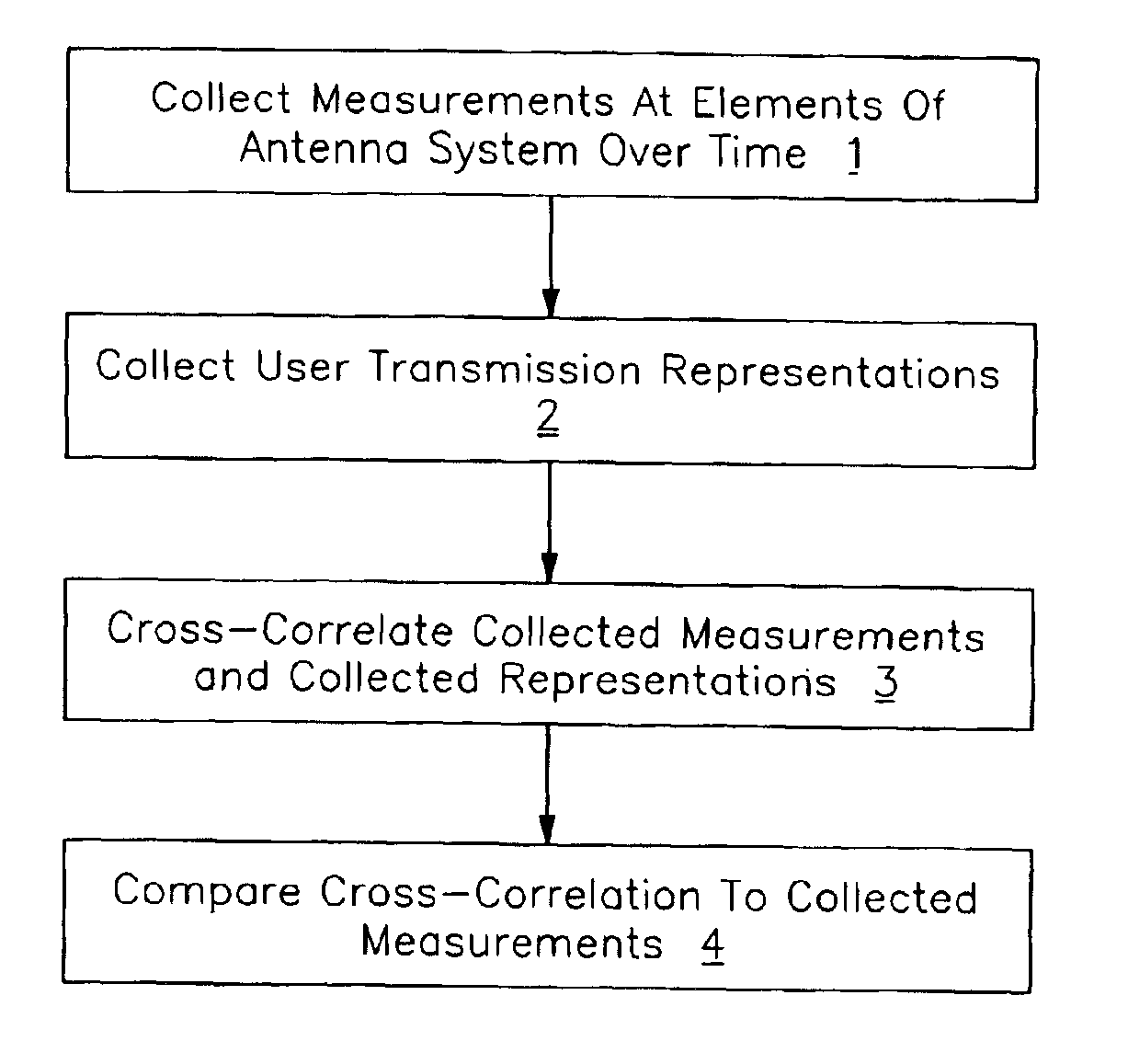
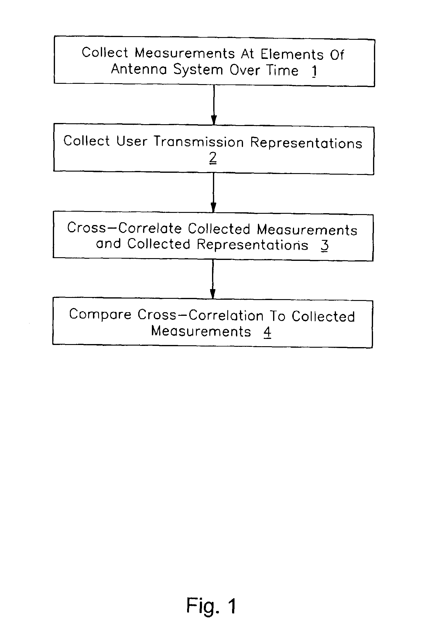
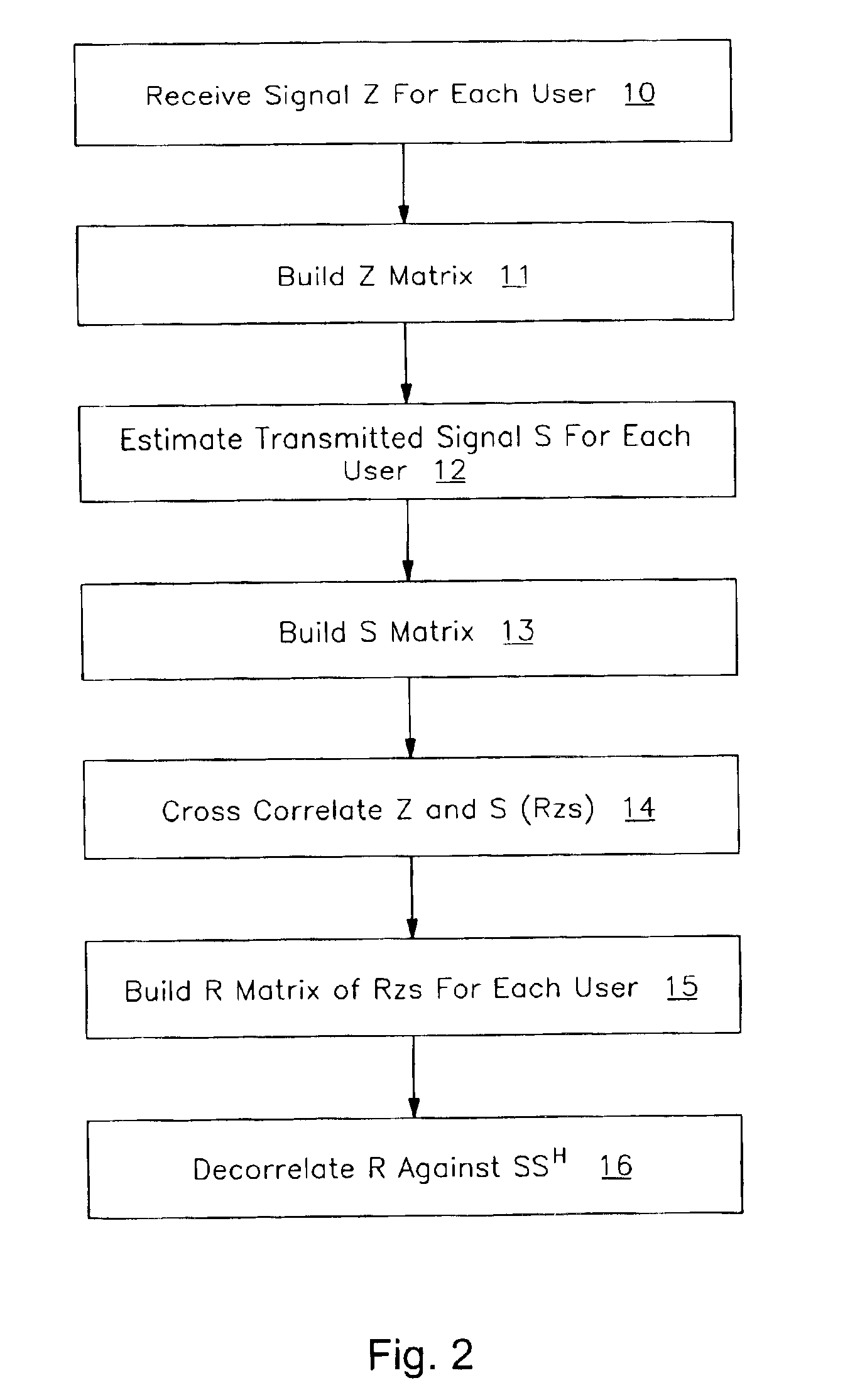
[0018]An unbiased spatial signature can be estimated by isolating the contribution of the user of interest from all of the other users. This can be done by collecting an estimate of the spatial signature for each user into columns of a matrix R, generated, for example, by cross-correlating the composite received signal with each user's corresponding estimated transmitted signal, and decorrelating with a matrix consisting of information from all of the users represented in the matrix R. As explained below, this can be expressed, in one example using hard symbol decisions, as Â=R(SSH)−1 or using soft symbol decisions as Â=(RzzR)(RRH)−1.

[0019]Adaptive Smart Antenna Processing

[0020]Embodiments of the invention relate to estimating spatial signatures used by a communications station to characterize communicating terminals. In some embodiments, the communications station is a base station communicating with many user terminals or remote terminals The spatial signatures can b...


PUM


Abstract

Spatial and temporal characteristics of received radio signals in a multiple user radio system can be estimated based on signals received from the users. In one embodiment, the invention includes measuring radio frequency signals received at different elements of an antenna system over time, the received signals corresponding at least in part to transmissions received from a system user, accumulating the signal measurements into a first matrix, generating a second matrix representing the transmissions of the system user, cross-correlating the first and second matrices to form a third matrix, and multiplying the third matrix with a product of the second matrix to form a fourth matrix in which the elements of the fourth matrix characterize the radio channel traversed by transmissions of the system user.

Description

BACKGROUND OF THE INVENTION[0001]1. Field[0002]The present invention relates to the field of wireless communications systems and, in particular, to determining spatial and temporal characteristics of signals received from transmitting wireless terminals.[0003]2. Description of the Prior Art[0004]Signal processing and a multiple antenna array can be used in a communication station (e.g., a base station) equipped with multiple antennas to either reject interference when receiving (e.g. on the uplink) or to deliver power in a spatially or spatio-temporally selective manner when transmitting (e.g., on the downlink). On the uplink, linear spatial processing can be used to apply amplitude and phase adjustments, typically but not necessarily in baseband, to each of the signals received at the antenna array elements. Such an adaptive smart antenna system can select (i.e., preferentially receive) the signals of interest while minimizing any signals or noise not of interest including interfer...

Claims


Application Information

Patent Timeline
IPC IPC(8): H04B7/04H04B7/08H04B7/06H04L25/02H04B1/707
CPCH04B7/0615H04B7/0854H04L25/0202H04B1/71052H04B7/0851
Inventor CHAUVIN, TODD H.KERR, ADAM B.KASAPI, ATHANASIOS A.
Owner INTEL CORP
Why Eureka
Try Eureka