Electronic projector capable of saving and displaying a user-defined logo

a projector and user-defined technology, applied in the field of electronic projectors, can solve the problem that users cannot access the image of the logo originally specified in the memory device, and achieve the effect of facilitating updating, and speeding up the display ra

Inactive Publication Date: 2005-09-27
MUSTEK SYSTEMS
View PDF13 Cites 11 Cited by
  • Summary
  • Abstract
  • Description
  • Claims
  • Application Information

AI Technical Summary

Benefits of technology

[0007]Accordingly, it is an object of the present invention to provide an electronic projector which allows users to save and update images data of a logo in the electronic projector in response to the control of the Central Process Unit.
[0008]Accordingly, an aspect of the invention provides an electronic projector capable of saving and displaying a user-defined logo. The electronic projector receives video signals from an image source device, such as a computer, a DVD, or a television for projecting the video signals onto a screen. The video signals from the image source device are converted to digital signals and then temporarily saved in a display buffer to speed up the display rate. The user-defined logo can be designed by a graphics application program or by freezing a static image from the video signals. After converting to digital signals, the user-defined logo is then saved in a non-volatile memory. A data access controller controls the display and update of the user-defined logo. When the user-defined logo is to be updated, the new user-defined logo is saved in the non-volatile memory to overwrite the previous logo. On the other hand, when the user-defined logo is to be displayed, the user-defined logo is copied from the non-volatile memory and then saved in the frame buffer to speed up the display rate. Eventually, with the logo update mechanism, the electronic projector can easily update and display a user-defined logo.

Problems solved by technology

However, since the conventional LCD projector does not provide an updated mechanism for the user to update the image data of the logo, so the users cannot access the image of the logo originally specified in the memory device 3.

Method used


Image

  • Electronic projector capable of saving and displaying a user-defined logo
  • Electronic projector capable of saving and displaying a user-defined logo
  • Electronic projector capable of saving and displaying a user-defined logo

Examples


Embodiment Construction

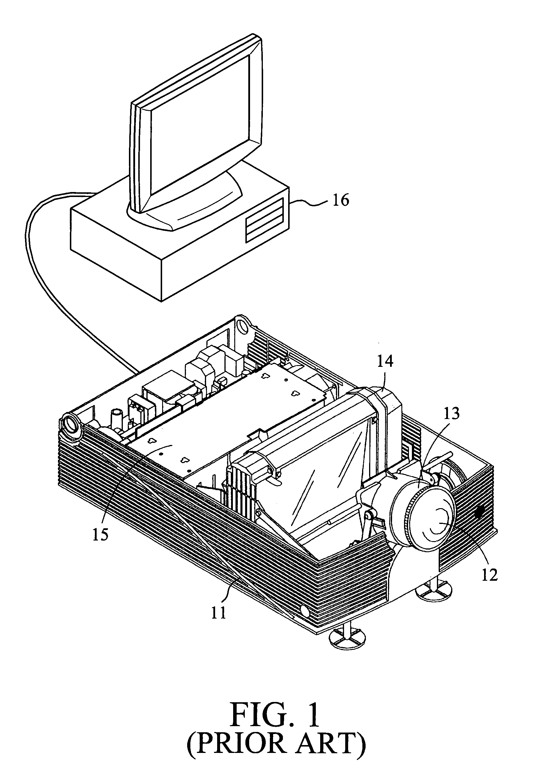
[0016]The logo update and display system for the electronic projector according to the preferred embodiment of the invention is shown in FIG. 3. The projector body 11 is connected to a computer 16 which can run a graphics application program for designing a logo or a graphics. The computer 16 can also transmit video signals to the projector body 11 for projecting a series of video images on to the screen. The video images or the user-defined logo are transmitted to the projector body 11 via the image input device 10. Since the video images and the user-defined logo are analog signals, so they must be converted into digital signals to be saved.

[0017]After converting to digital signals, the RGB color components of the video images and the user-defined logo are then analyzed and saved in associated Random Access Memory (RAM) 20, 22, and 24 respectively. The RGB color components of the image data are then processed by the pre-processor 30 for scaling up / down the images, or converting th...


PUM


Abstract

An electronic projector capable of saving and displaying a user-defined logo is provided. The electronic projector receives video signals from an image source device, such as a computer, a DVD, or a television for projecting the video signals onto a screen. The video signals from the image source device are converted to digital signals and then temporarily saved in a display buffer to speed up the display rate. The user-defined logo can be designed by a graphics application program or by freezing a static image from the video signals. After converting to digital signals, the user-defined logo is then saved in a non-volatile memory. A data access controller controls the display and update of the user-defined logo. When the user-defined logo is to be updated, the new user-defined logo is saved in the non-volatile memory to overwrite the previous logo. On the other hand, when the user-defined logo is to be displayed, the user-defined logo is copied from the non-volatile memory and then saved in the frame buffer to speed up the display rate. Eventually, with the logo update mechanism, the electronic projector can easily update and display a user-defined logo.

Description

CONTINUATION-IN PART APPLICATION DATA[0001]The present application is a continuation-in-part of a co-pending Continued Prosecution Application based on parent U.S. application Ser. No. 08 / 933,201, filed on Dec. 18, 1997, now U.S. Pat. No. 5,941,538 invented by Lee et al.BACKGROUND OF THE INVENTION[0002]A. Field of the Invention[0003]The present invention relates to an electronic projector, especially to a Liquid Crystal Display (LCD) projector capable of saving and displaying user-defined logos.[0004]B. Description of the Related Art[0005]There are various types of LCD projectors available on the market. Refer to FIG. 1 for showing the structure of the conventional LCD projectors. It includes a projector body 11, a main focusing lens 12, an optical projection system 13, a LCD display panel 14, and a lamp assembly 15. Generally, these LCD projectors can only display whatever video signals transmitted from an image source device 16, such as a computer, a television, or a DVD, etc. In ...

Claims


Application Information

Patent Timeline
Patent Type & Authority Patents(United States)
IPC IPC(8): G09G3/36G09G5/00H04N5/44H04N5/74
CPCG09G5/00H04N21/4312H04N5/74H04N21/4122H04N5/4448G09G2340/02
Inventor LEE, TIAN-QUEY
Owner MUSTEK SYSTEMS
Why Eureka
Try Eureka