Device and method for detecting and preprocessing weights acting on a vehicle seat

Inactive Publication Date: 2005-09-27
BAG BIZERBA AUTOMOTIVE GMBH
View PDF24 Cites 15 Cited by
  • Summary
  • Abstract
  • Description
  • Claims
  • Application Information

AI Technical Summary

Benefits of technology

[0021]It is therefore an object of the invention to form a device of the type described at the beginning in such a way that it can be used in particular in conditions which are very difficult in terms of measuring technology, and in particular under the other special ambient conditions within a vehicle, and the weighing signal of which is substantially uninfluenced by this and can provide a reliable parameter for airbag activation over long periods of time.

Problems solved by technology

In the course of introducing airbags as standard for the passenger seat in motor vehicles there arises the problem of detecting the occupancy of the seat, so that the passenger airbag is released for firing only in those cases in which the seat is occupied.
Firing of the passenger airbag when the passenger seat is not occupied not only has the consequence that an additional increase in pressure in the vehicle is unnecessarily caused in the event of an accident by the firing of the passenger airbag, but also that, due to the integration of the passenger airbag into the dashboard, considerable repair measures are necessary in the passenger compartment of the vehicle following firing of the airbag.
Various problems which have been observed when airbags are fired with small children or youngsters traveling on the passenger seat have ultimately led to the requirement that, in the event of an accident, an airbag must be operated in a way which is adapted to the person sitting on the vehicle seat.
This gives rise to the problem of determining the necessary data for firing the airbag in a way appropriate for requirements.
It is a disadvantage of this solution that changes in the spring constant of the seat suspension (aging, use) lead to an additional zero drift of the weighing signal of the sensor elements.
In addition, considerable measuring errors occur when the vehicle accelerates or decelerates, and have to be corrected in a complex way.
An adverse effect of these measuring errors is that they correspond to interference signals with a long period / low frequency.
As a result, a more time-consuming correction has to be performed, making the measuring system intrinsically slow to respond.
In addition, when the vehicle is inclined, a great measuring error is obtained, and can only be corrected with considerable effort.
A particular disadvantage of this solution is that the seat rails have to be disposed higher above the floor of the vehicle than would otherwise be necessary without the sensors.
This, however, impairs the headroom for the occupants of the vehicle.
These strain-gage transducers achieve very high degrees of accuracy, but can be protected against ambient influences only with great effort, since the strain-sensitive sensor elements are located directly on the elastically deforming part and covering of the sensors has the concomitant effect of force bypasses, which have direct adverse effects on the properties of the transducer.
These prove to be unsuitable under extreme ambient conditions, in particular such as occur for example in a motor vehicle, since they are too susceptible to interference.
In terms of measuring technology, the vehicle interior is extremely problematical, since not only do interference signals of the engine ignition (electromagnetic fields with high field strengths) occur to a considerable extent and have to be eliminated in signaling terms, but it is also necessary with respect to the functional capability of sensors that are to be used to take into account extreme vibrations, temperature conditions in a range from, for example, −40° C. to +85° C., rapid temperature changes and also atmospheric humidity ranging right up to the dew point.

Method used


Image

  • Device and method for detecting and preprocessing weights acting on a vehicle seat
  • Device and method for detecting and preprocessing weights acting on a vehicle seat
  • Device and method for detecting and preprocessing weights acting on a vehicle seat

Examples


Embodiment Construction

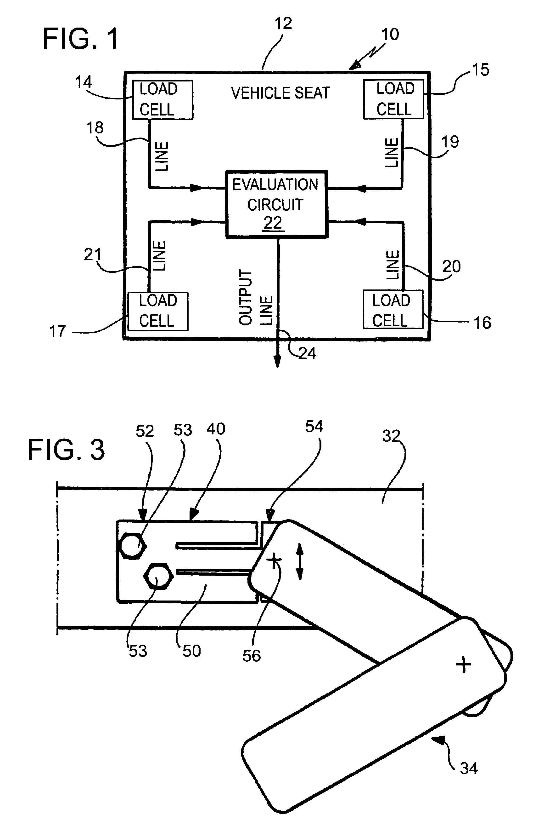
[0118]FIG. 1 schematically shows a device 10 according to the invention for detecting and evaluating a weight which acts on a vehicle seat 12 (only indicated here).

[0119]In the present example, the device 10 according to the invention comprises four loads cells 14, 15, 16 and 17, which are disposed in the region of the four corners of the sitting area of the vehicle seat 12.

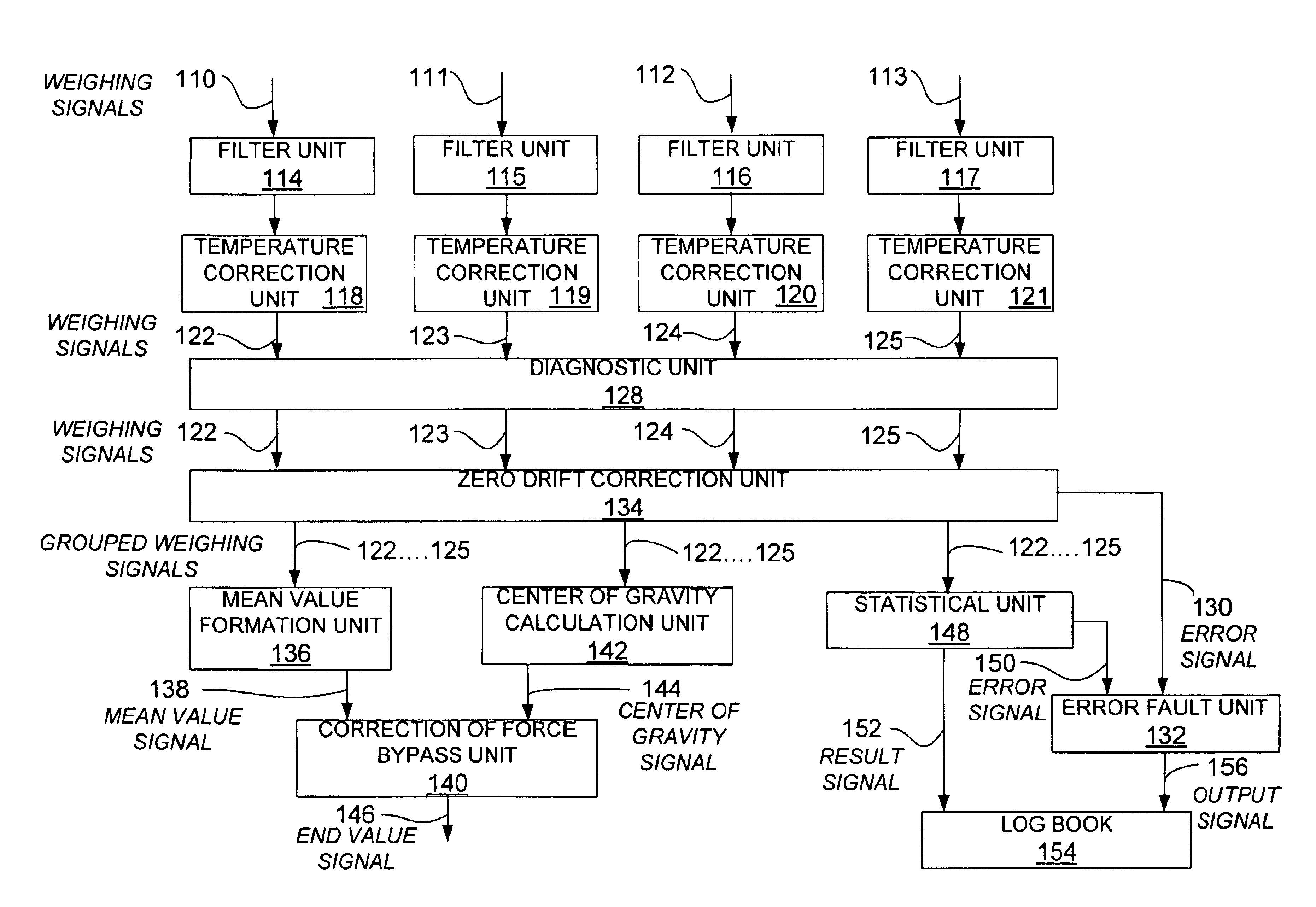
[0120]The loads cells 14 to 17 are connected via signal lines 18, 19, 20 and 21 to an evaluation circuit 22, which receives and preprocesses the weighing signals supplied by the load cells. Once preprocessing has taken place, which will be described still further below, the evaluation circuit provides via a signal output line 24 an output signal for a downstream control circuit or the electronics of the vehicle, which assume(s) the further routing of the signal to the airbag control electronics, possibly in an additionally preprocessed form.

[0121]The signal output line 24 may be part of the vehicle's own signal b...


PUM


Abstract

In order to form a device for detecting and preprocessing weights acting on a vehicle seat in such a way that it can be used in particular in conditions which are very difficult in terms of measuring technology, and in particular under the other special ambient conditions within a vehicle, and the weighing signal of which is substantially uninfluenced by this and can consequently provide a reliable parameter for airbag activation, it is proposed that this device comprises at least three load cells, which are disposed on load-carrying parts of the vehicle seat at corner points of an imaginary polygonal area and in each case generate a weighing signal corresponding to the weight, and an electronic evaluation circuit, which receives and preprocesses the weighing signals of the load cells and generates an output signal based on the weighing signals, the evaluation circuit comprising an evaluation function with which a localization of the center of gravity of the weight acting on the vehicle seat can be carried out from the individual weighing signals of the at least three load cells, and the evaluation circuit comprising a correction function, with which force bypasses can be taken into account in the forming of the output signal.

Description

[0001]The present disclosure relates to the subject matter disclosed in German application No. 101 20 978.9 of May 1, 2001, which is incorporated herein by reference in its entirety and for all purposes.[0002]This application is a continuation of PCT / EP02 / 04768, which claims priority to German application No. 101 20 978.9.BACKGROUND OF THE INVENTION[0003]The invention relates to a device for detecting and preprocessing weights acting on a vehicle seat.[0004]In the course of introducing airbags as standard for the passenger seat in motor vehicles there arises the problem of detecting the occupancy of the seat, so that the passenger airbag is released for firing only in those cases in which the seat is occupied. Firing of the passenger airbag when the passenger seat is not occupied not only has the consequence that an additional increase in pressure in the vehicle is unnecessarily caused in the event of an accident by the firing of the passenger airbag, but also that, due to the integ...

Claims


Application Information

Patent Timeline
IPC IPC(8): B60R21/01B60R21/015
CPCB60R21/01516
Inventor SELIG, KLAUS PETERWURSTER, KLAUS
Owner BAG BIZERBA AUTOMOTIVE GMBH
Why Eureka
Try Eureka