
Bone screw for use in orthopaedic surgery

Inactive Publication Date: 2005-09-27
ORTHOFIX SRL
View PDF12 Cites 136 Cited by
  • Summary
  • Abstract
  • Description
  • Claims
  • Application Information

AI Technical Summary

Benefits of technology

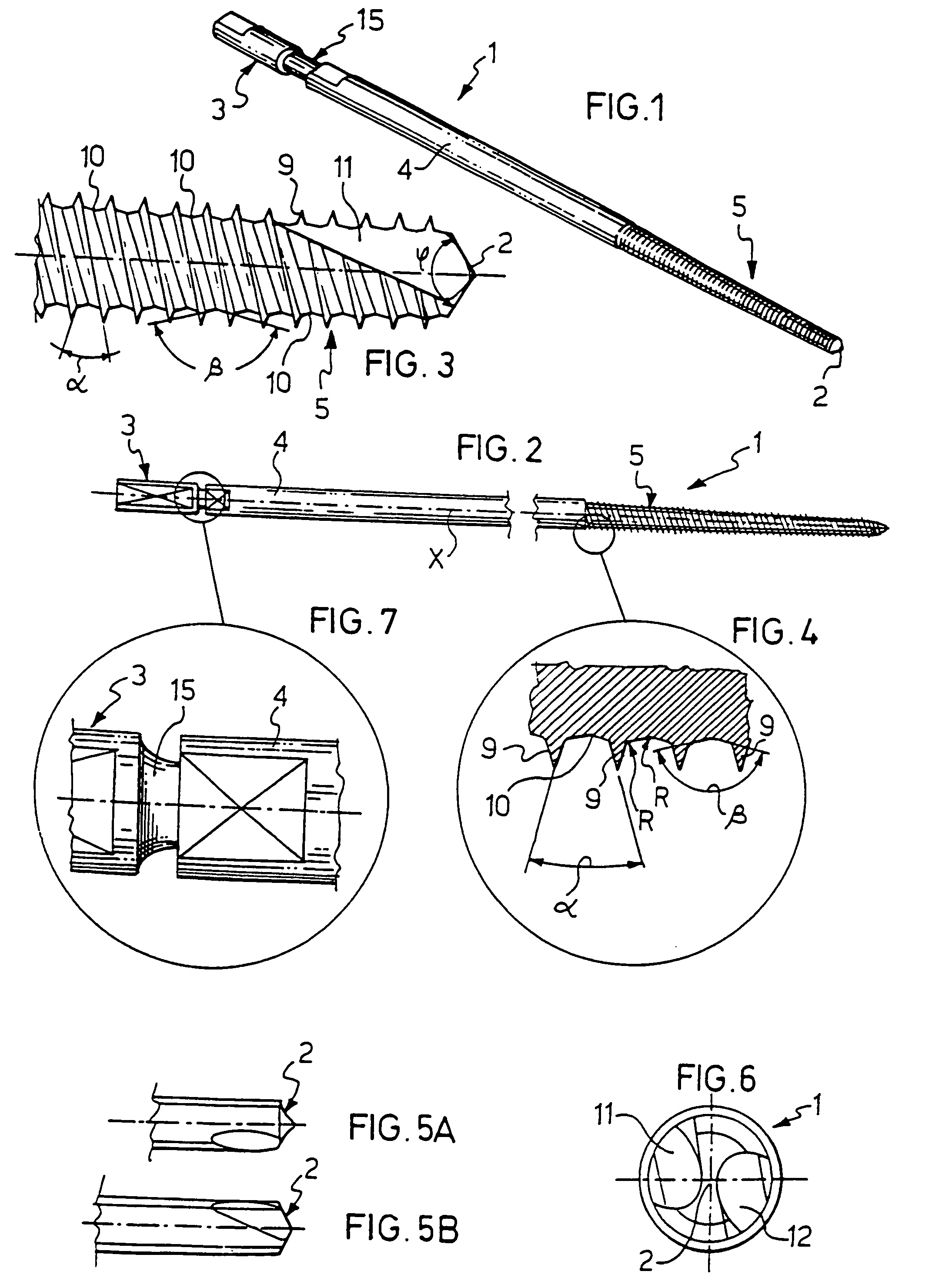
[0017]The concept of this invention is one of providing a bone screw with a self-tapping threaded portion which includes at least one constant pitch section comprised of threads having a triangular cusp profile in cross- section and being separated from each other by a shaped bottom land with a concave profile defined by two countersloping planes. This allows the elongate conical profile of the threaded portion to be put to best use, and affords a large area of contact with the bone effective to reduce the specific loading pressure.

Problems solved by technology

Furthermore, providing a hole in the bone prior to inserting the screw, according to the screw diameter, lowers the insertion temperature which, if excessively high, can hurt the particular bone connective tissue around the screw, as described in an article “Cancellous Bone Screw Thread Design and Holding Power”, Journal of Orthopaedic Trauma, Vol. 10, No. 7, pages 462–469.
In particular, it has been found that conventional thread profiles have a common drawback in that they only provide an inferior distribution of C the stress from the force applied to penetrate the cortical portion of the bone.

Method used


Image

  • Bone screw for use in orthopaedic surgery
  • Bone screw for use in orthopaedic surgery

Examples


Embodiment Construction

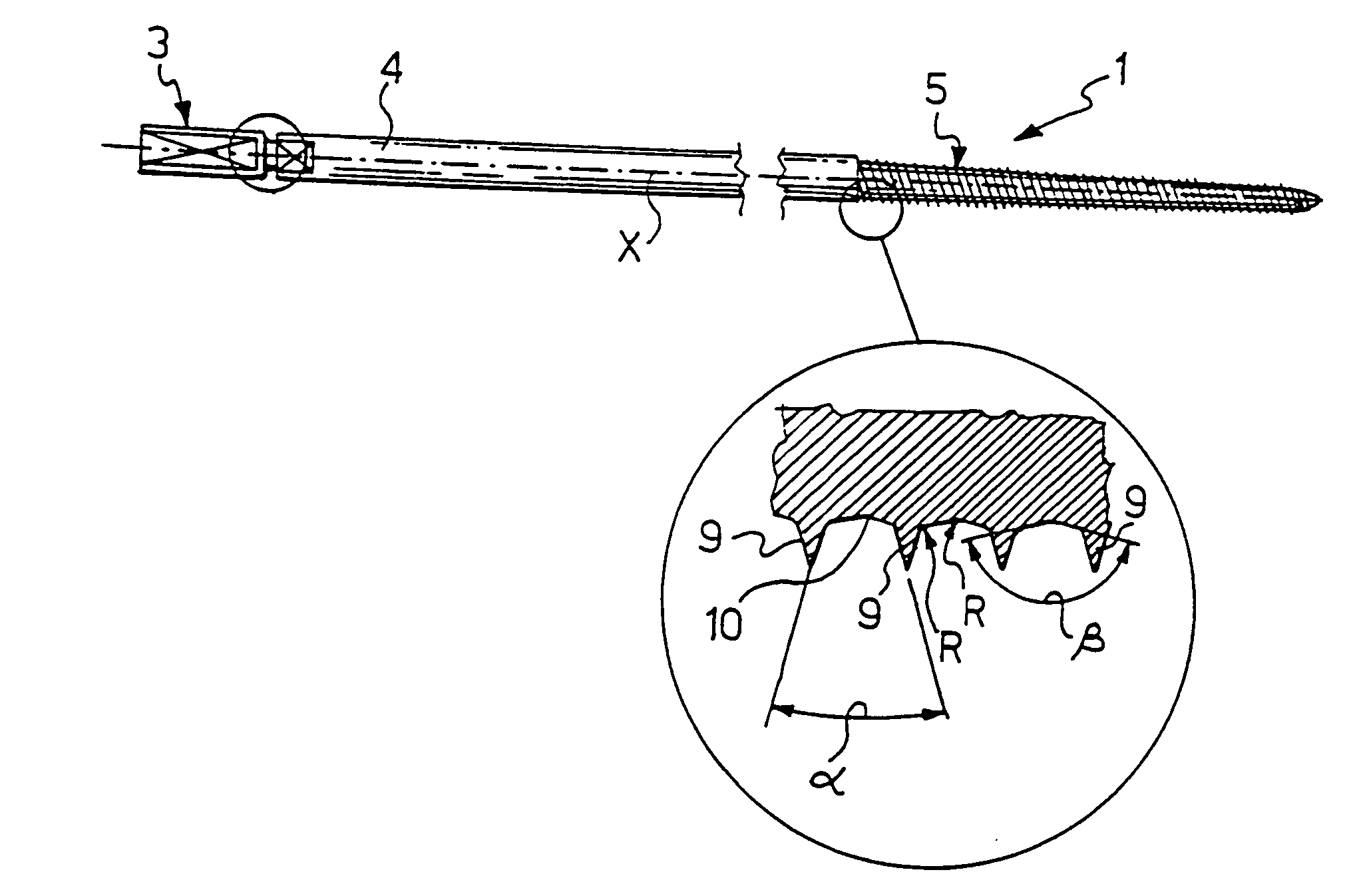
[0027]Referring to the drawing views, in particular to the example of FIG. 1, generally and schematically shown at 1 is a bone screw according to this invention intended for use in human or animal orthopaedic surgery with devices for the external fixation of bone fractures.

[0028]The screw 1 has a tip end 2 adapted to be implanted by a surgeon into the cortical portion of a bone, and then driven in a threaded manner by means of a tool applied to a head end 3 of the screw.

[0029]The screw 1 comprises a shank 4 and a threaded portion 5 formed integral with the shank 4. The threaded portion 5 has an elongate conical shape and the same diameter as the shank 4 at its region adjoining the shank, to then taper slightly in the direction towards the tip end 2. The threaded portion 5 accounts for about one third of the screw overall length. However, another length ratio of the threaded portion 5 to the shank 4 could be chosen instead.

[0030]Advantageously, the screw is of the self-tapping type i...


PUM


Abstract

The invention relates to an improved bone screw for use in orthopaedic surgery, in particular with external fracture fixation devices, of the type which comprises ahead (3), a shank (4), and a threaded portion (5) tapering towards a tip (2) at the opposite end from the head (3). Advantageously, the threaded portion (5) has at least one constant pitch section comprising threads (9) which have a triangular cusp-like profile in cross section and are separated from each other by a shaped bottom land with a concave profile (10) defined by two countersloping planes.

Description

TECHNICAL FIELD[0001]This invention relates to an improved bone screw for use in orthopaedic surgery, specifically in devices for the external fixation of bone fractures.[0002]More particularly, the invention relates to a screw having a head or application end, a shank, and a threaded portion, which tapers towards a tip at the opposite end from the application end.BACKGROUND ART[0003]As is well known, a variety of external fixation devices are currently employed with increasing frequency in human as well as veterinary orthopaedic surgical procedures for treating complex fractures and / or fractures associated with serious damage to the cutaneous tissue.[0004]Devices of this kind allow broken bones to be consolidated and reduced in highly critical areas of the human bony structure, especially near joints.[0005]Customarily, the opposite ends of an external fixation device are secured to respective undamaged portions of a broken bone by means of bone screws set in the bone itself. Such i...

Claims


Application Information

Patent Timeline
IPC IPC(8): A61B17/86A61B17/68F16B25/00F16B25/10A61B17/58
CPCA61B17/8625A61B17/8635F16B25/103
Inventor VENTURINI, DANIELE
Owner ORTHOFIX SRL
Learn More