Water collection irrigation device for fruit and vegetable planting
The technology of a watering device and a water collecting device is applied in the field of agricultural irrigation, which can solve the problems of no water collecting device, large overall quality, insufficient fruits and vegetables, etc., and achieve the effect of ensuring cleanliness and filtration performance.
- Summary
- Abstract
- Description
- Claims
- Application Information
AI Technical Summary
Problems solved by technology
Method used
Image
Examples
Embodiment 1
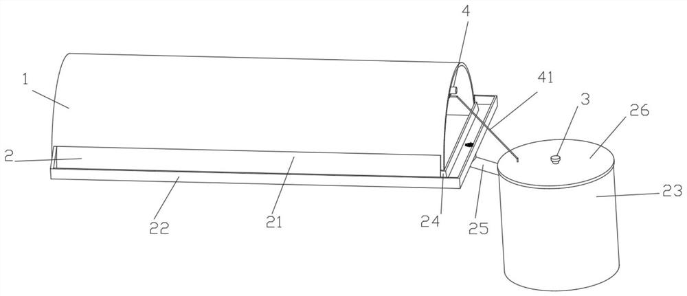
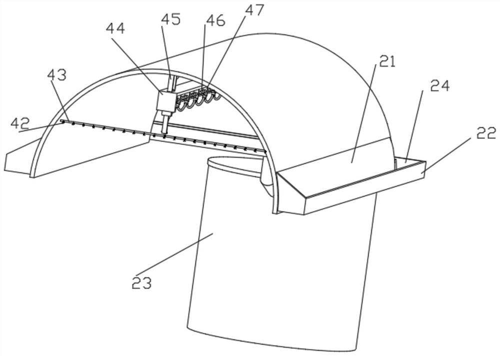
[0037] Such as figure 1 , 2 A kind of water collecting irrigation device for fruit and vegetable planting shown in 6, comprises planting shed 1, and planting shed 1 is connected with the water collecting device 2 that is used for rainwater collection, and water collecting device 2 comprises arc lamination plate 21, U-shaped block 22, collecting Water tank 23, U-shaped groove 24, L-shaped pipe 25 and cover plate 26, the inner wall of U-shaped block 22 is fixedly connected with arc-shaped fitting plate 21, and arc-shaped fitting plate 21 is in contact with the front and rear outer walls of planting greenhouse 1, U Shaped block 22 is provided with U-shaped groove 24, and the right end of U-shaped block 22 is fixedly connected with L-shaped pipe 25, and the bottom of L-shaped pipe 25 is fixedly connected with water collecting box 23, and water collecting box 23 is installed below the ground, and the bottom of water collecting box 23 The top is movably connected with a cover plate...
Embodiment 2
[0041] Embodiment 2 is a further improvement to Embodiment 1.
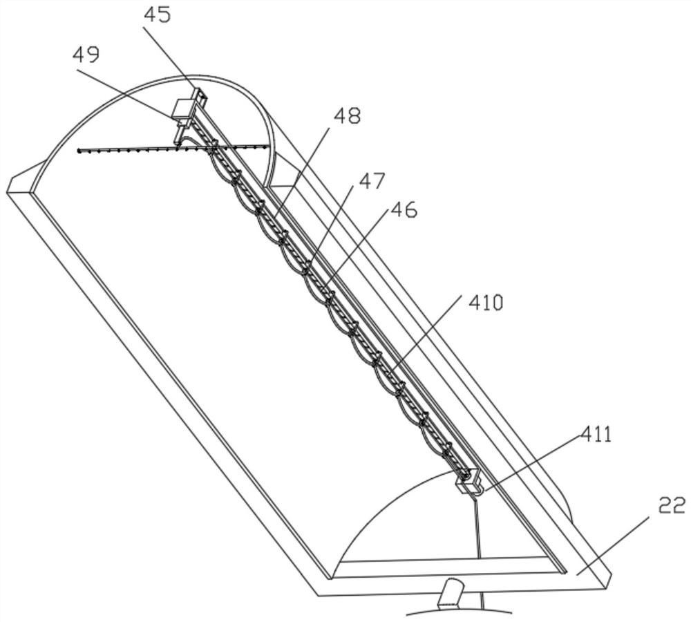
[0042] Such as figure 1 , 2, 3, 4, 6, 7, and 9 shown irrigation structures 4 include water inlet hose 41, nozzle 42, horizontal pipe 43, n-shaped mounting plate 44, connecting block 45, threaded rod 46, middle slide plate 47, support rod 48, the second slide plate 49, steel rope 410, drive motor 411, connecting sleeve 412, lock pin 413, L-shaped installation block 414, water pump 415, T-shaped slot 416, T-shaped plug 417 and middle hose 418, The top of the n-shaped mounting plate 44 is uniformly fixedly connected with a connection block 45, and one end of the n-shaped mounting plate 44 is fixedly installed with a driving motor 411, and the output end of the driving motor 411 is fixedly connected with a threaded rod 46, and the threaded rod 46 is threadedly connected with a second Sliding plate 49, steel rope 410 is fixedly connected between the right side wall of the second sliding plate 49 and the right end inn...
Embodiment 3
[0045] Embodiment 3 is a further improvement to Embodiment 1.
[0046] Such as Figure 5 , 8 The shown filter structure 5 comprises a push plate 51, a groove 52, a filter plate 53, a rotating shaft 54, a drive fan blade 55 and a support ring 56, the groove 52 is provided at the bottom of the U-shaped groove 24, and the upright of the L-shaped pipe 25 The upper end of the inner wall of the part is fixedly connected with a support ring 56, and the top of the support ring 56 is fitted and slidably connected with a filter plate 53, and the outer wall of the filter plate 53 is fitted and slidably connected with the inner wall of the groove 52, and the middle end of the filter plate 53 is fixed by The connected bearing is rotatably connected with a rotating shaft 54, and the top of the rotating shaft 54 is evenly fixedly connected along the circumferential direction with a push plate 51 that is fitted and slidably connected to the top of the filter plate 53, and the lower end of ...
PUM
 Abstract
Description
Claims
Application Information
 - Generate Ideas
- Intellectual Property
- Life Sciences
- Materials
- Tech Scout
- Unparalleled Data Quality
- Higher Quality Content
- 60% Fewer Hallucinations
Browse by: Latest US Patents, China's latest patents, Technical Efficacy Thesaurus, Application Domain, Technology Topic, Popular Technical Reports.
© 2025 PatSnap. All rights reserved.Legal|Privacy policy|Modern Slavery Act Transparency Statement|Sitemap|About US| Contact US: help@patsnap.com


