
Automatic balance adjusting centrifugal apparatus

a centrifugal machine and automatic technology, applied in the direction of centrifuges, rotating bodies, etc., can solve the problems of reducing the life of the centrifugal machine, no safety device for protecting specimens and centrifugal machines, etc., to prevent the destruction of specimens and extend the life of the machin

Inactive Publication Date: 2005-09-27
HANLAB CORP
View PDF29 Cites 20 Cited by
  • Summary
  • Abstract
  • Description
  • Claims
  • Application Information

AI Technical Summary

Benefits of technology

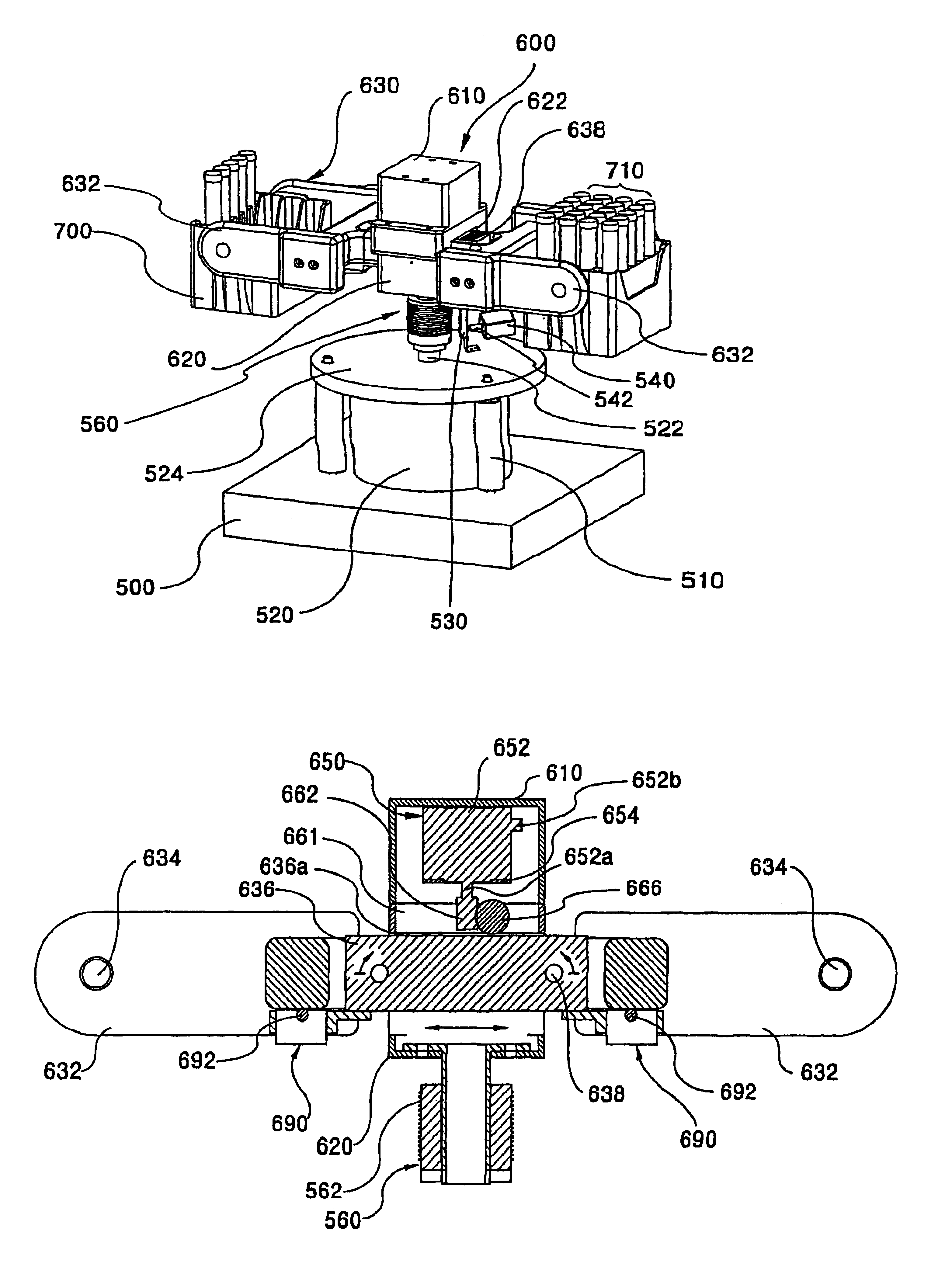
[0007]The present invention has been made to solve the above mentioned problems and, therefore, it is an object of the present invention to provide a centrifugal machine of automatic balance type for detecting an unbalance in a specimen mounted on a rotor lever before every centrifugal machining, and for moving horizontally the rotor lever itself or a balance weight member according to detected results, maintaining an automatic balance, thereby preventing destruction of a specimen due to an unbalance of the rotor and extending life of the machine.
[0008]It is another object of the present invention to provide a centrifugal machine of automatic balance type for displaying a status of impossibility that automatic balance condition is not maintained due to a severe load unbalance so that a user recognizes the status, thereby preventing destruction of a specimen and extending life of the machine.
[0013]Furthermore, the electrical connection means is further comprised of a displaying means for giving a warning in case that a load difference between both ends of the rotor lever exceeds a predetermined value. In case that the load difference exceeds the predetermined value as a result of the load calculation, the controlling means controls to drive the displaying means, thereby preventing centrifugal machining under inadequate condition of excess load difference.

Problems solved by technology

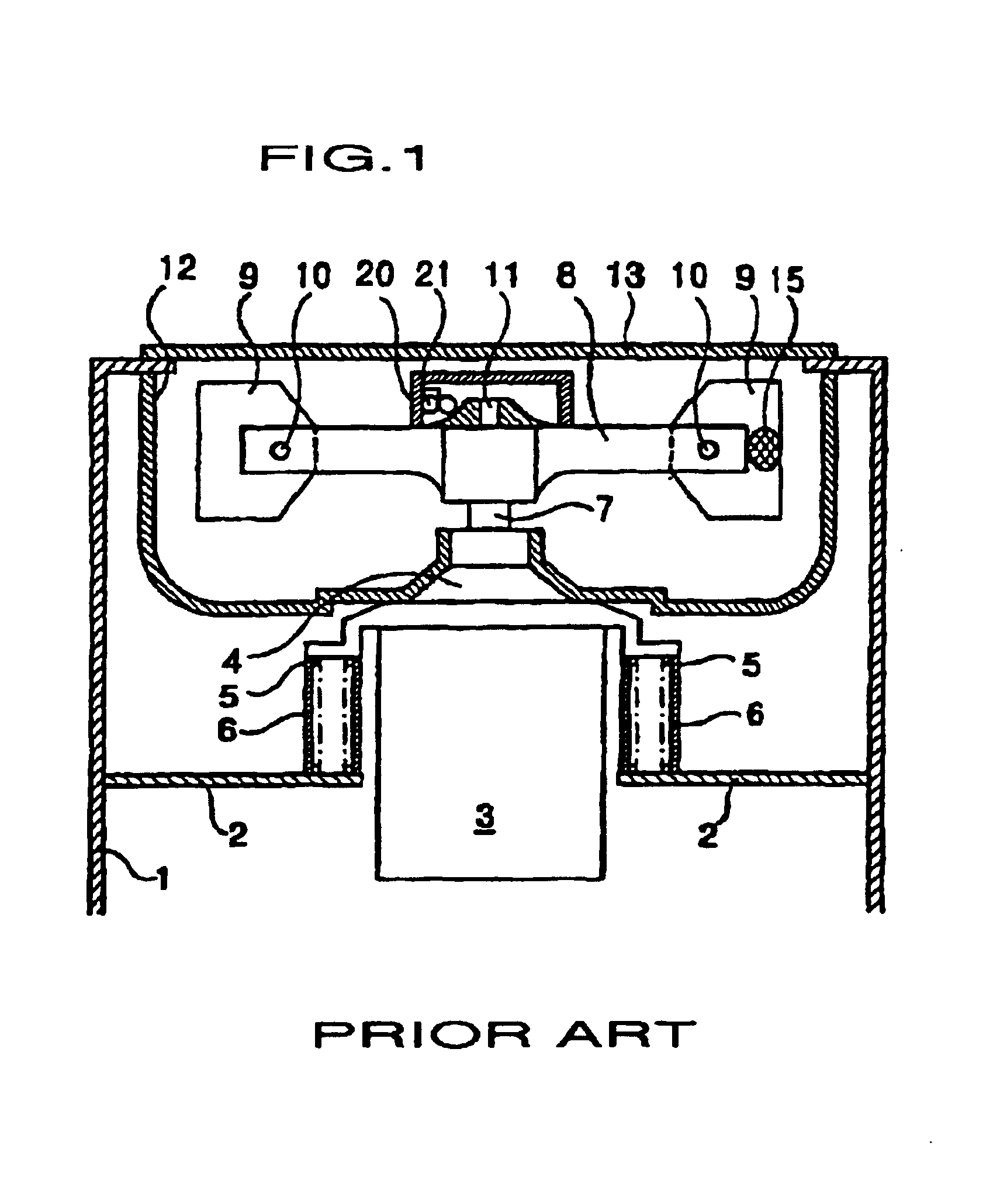
According to the foregoing related centrifugal machine of automatic balance type, an unbalance generated from a load difference between specimens that is within a predetermined range can be corrected automatically, but in case of centrifugal machining a specimen beyond such range, a problem that there is no safety device for protecting a specimen and a centrifugal machine.
If a user does not pay a proper attention like this, an excessive vibration may be generated in a rotational shaft and a specimen is destroyed, and in worst case, a bearing and a driving part including a motor may be broken down, so that life of a centrifugal machine is reduced

Method used


Image

  • Automatic balance adjusting centrifugal apparatus
  • Automatic balance adjusting centrifugal apparatus
  • Automatic balance adjusting centrifugal apparatus

Examples


Embodiment Construction

[0026]A preferred embodiment of a centrifugal machine of automatic balance type according to the present invention will now be described with reference to the accompanying drawings. The matters defined in the description such as a detailed construction and elements of a circuit are nothing but the ones provided to assist in a comprehensive understanding of the invention. Thus, it is apparent that the present invention can be carried out not limited to those defined matters. Also, well-known functions or constructions are not described in detail since they would obscure the invention in unnecessary detail.

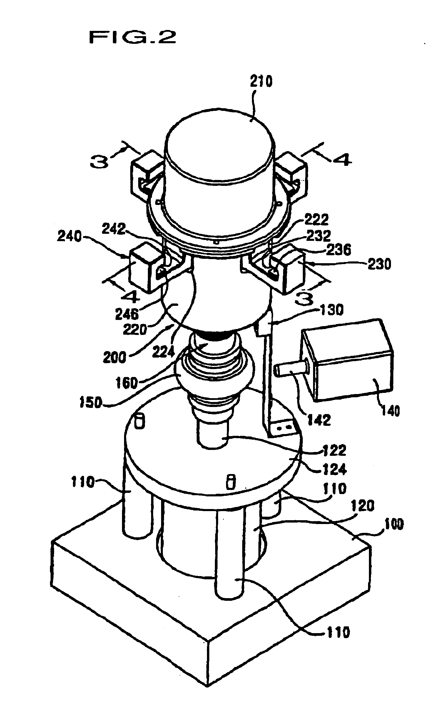
[0027]FIG. 2 is a perspective view schematically showing appearance of a centrifugal machine of automatic balance type according to one embodiment of the present invention, taking an example where two rotor levers are adopted. As shown in FIG. 2, a centrifugal machine of automatic balance type according to one embodiment of the present invention is roughly comprised of a base 100; a...


PUM


Abstract

A centrifugal machine of automatic balance type is provided for detecting an unbalance in a specimen mounted on a rotor lever before every centrifugal machining, and for moving horizontally the rotor lever according to detected results, maintaining automatic balance, thereby preventing destruction of a specimen due to an unbalance of the rotor, and extending the life of the machine.

Description

TECHNICAL FIELD[0001]The present invention relates to a centrifugal machine of automatic balance type, and particularly to a centrifugal machine of automatic balance type for detecting a load unbalance between specimens mounted on a rotor lever and for moving horizontally the rotor lever itself or a balance weight member according to detected results, thereby maintaining an automatic balance before every centrifugal machining.BACKGROUND ART[0002]Generally, a centrifugal machine is an apparatus for rotating a rotor containing a specimen in high speed, giving the specimen high centrifugal acceleration, so that a specimen of high density is positioned on an outer layer in a radial direction while a specimen of low density is positioned on an inner layer in a radical direction, thereby separating an ingredient thereof[0003]FIG. 1 is a cross-sectional view schematically representing a related centrifugal machine of automatic balance type. As shown in FIG. 1, a related centrifugal machine...

Claims


Application Information

Patent Timeline
Patent Type & Authority Patents(United States)
IPC IPC(8): B04B9/14B04B9/00B04B5/02F16F15/36B04B13/00
CPCB04B5/0421B04B9/146F16F15/36B04B13/00
Inventor BAIK, DOU-HARYU, HEUI-GEUN
Owner HANLAB CORP
Learn More