
Magnetic signal recording method and magnetic recording-reproduction apparatus

a magnetic recording and signal recording technology, applied in the field of magnetic signal recording, can solve the problems of insufficient temperature distribution having the oblong shape recited in reference 1 to be used in high density recording, and the inability to achieve the recording-reproduction process having high bit density, etc., to achieve the effect of improving the s/n of the reproduction signal and low cos

Inactive Publication Date: 2005-09-20
SHARP KK
View PDF10 Cites 2 Cited by
  • Summary
  • Abstract
  • Description
  • Claims
  • Application Information

AI Technical Summary

Benefits of technology

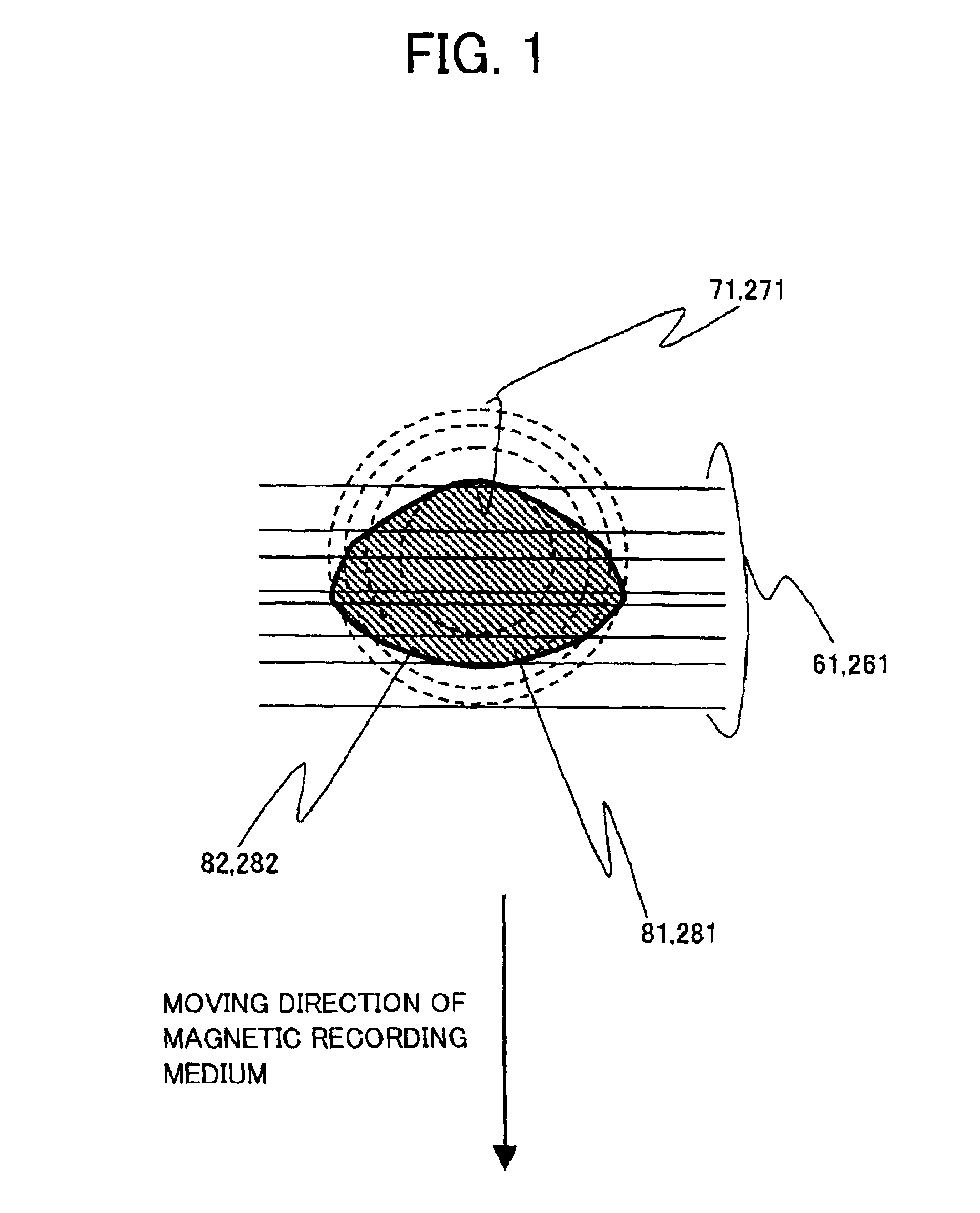
The present invention provides a magnetic signal recording method that improves the signal-to-noise ratio (S / N) of reproduction signals in high-density recording. This is achieved by approximating the shape of the recordable region on the magnetic recording medium to the shape of the contour lines of the recording magnetic field distribution. The magnetic recording head used in the method has a rectangular-shaped recording magnetic field that matches the shape of the contour lines. This results in a rectangular shape of the edge of the recordable region, which is the position where the highest coercive force is located. The use of this magnetic recording head with a single-magnetic polar head or a magnetic recording head with a wider main magnetic pole and a narrower track pitch also contributes to the improvement of the S / N of the reproduction signal. The method is cost-effective and easy to implement.

Problems solved by technology

Therefore, the creation of the magnetic bit in a non-rectangular shape as described above causes such a problem that an S / N of a signal is adversely affected, thereby giving a drawback to achieve the recording-reproduction process having high bit density.
However, the Reference 1 fails to take the magnetic field distribution of the magnetic recording head into consideration.
Thus, it is proved that the temperature distribution having the oblong shape recited in the Reference 1 is not adequate to be used in the high density recording.
In addition, the formation of the temperature distribution having the oblong shape heats up a large area of the magnetic recording medium, thereby having such a disadvantage that a large amount of electric power is consumed.
This means that the shape of the magnetic bit recorded may not be constant even if a short magnetic bit is recorded for a sake of high density recording.
However, the statement that the coercive force is constant in the vicinity of the recording temperature is not enough to explain the feature.
Thus, the method of the Reference 1 is inadequate for the high density recording and reproduction, in terms of the S / N.
Furthermore, in the method of the Reference 1, extra power is required for a laser used for the recording.
Moreover, in case where the magnetic recording medium recited in the Reference 1 is used in the common disc drive, the track pitch is determined by the width of the gap of the magnetic recording head, so that it is impossible to make the best of the high track density of the optical recording.

Method used


Image

  • Magnetic signal recording method and magnetic recording-reproduction apparatus
  • Magnetic signal recording method and magnetic recording-reproduction apparatus
  • Magnetic signal recording method and magnetic recording-reproduction apparatus

Examples


first embodiment

[0085][First Embodiment]

[0086]Described below is an embodiment of the present invention.

[0087]It should be noted that, in the present embodiment, explained is a case where (a) used as a recording medium is a magnetic recording medium that includes an alloy thin film, as a magnetic recording layer, that has an axis of easy magnetization in a vertical direction with respect to a film surface of the magnetic recording medium, and (b) provided as a magnetic recording head is a single-magnetic polar head having a main magnetic pole in a substantially rectangular shape.

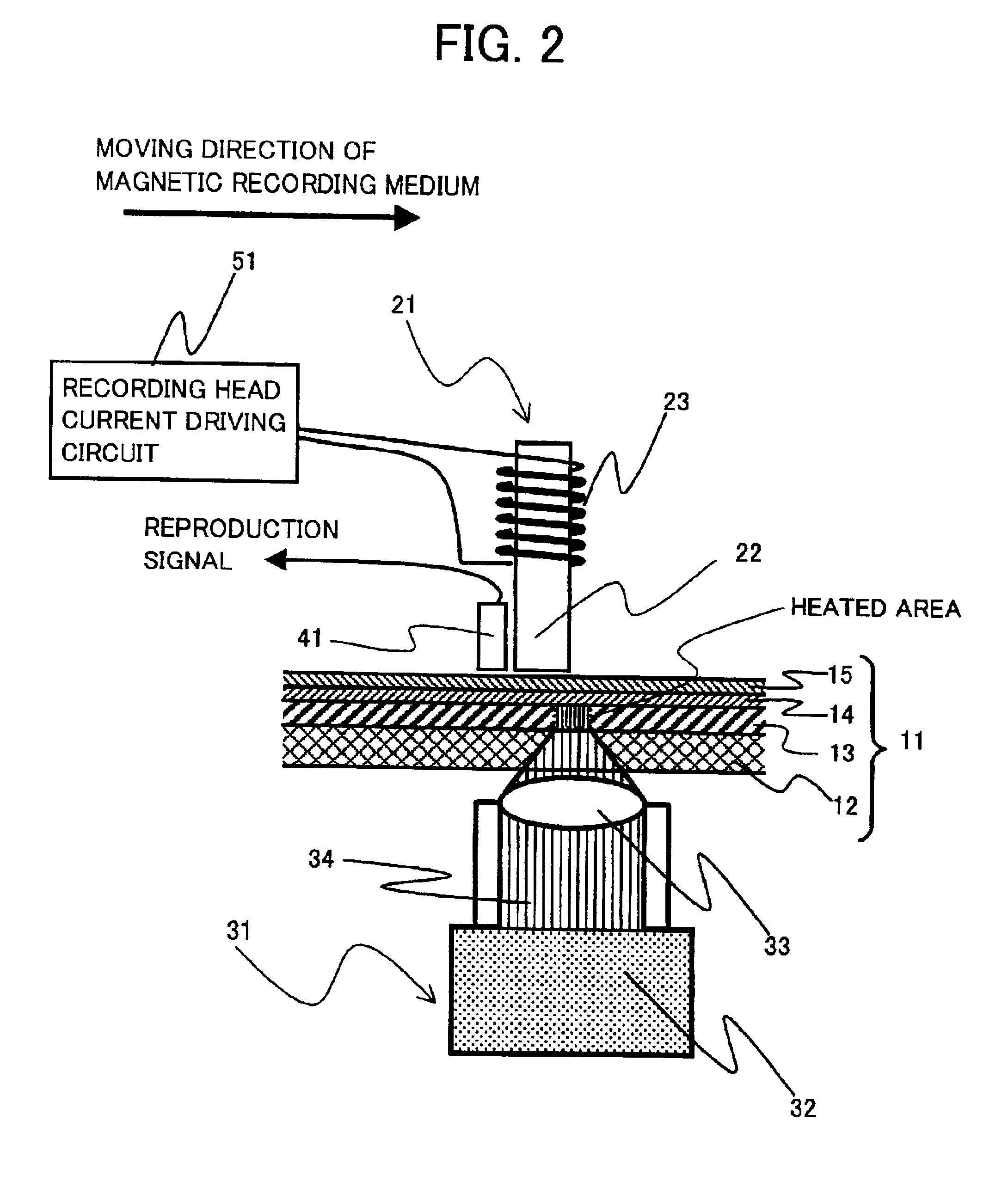
[0088]A magnetic recording-reproduction apparatus of the present embodiment has such a configuration that, as shown in FIG. 2, a single-magnetic polar head 21 and an optical local heater 31 are disposed face to face, while sandwiching a magnetic recording medium 11 in between.

[0089]The magnetic recording medium 11, as indicated by an arrow in FIG. 2, is moved in a parallel direction with respect to the film surface. A recor...

second embodiment

[0138][Second Embodiment]

[0139]Another embodiment of the present invention is described below.

[0140]It should be noted that, in the present embodiment, explained is a case where a ring head having a recording gap in a substantially rectangular shape is used as a magnetic recording head. Moreover, for convenience to explain, sections having the same function as those of the first embodiment are labelled in an identical manner and their explanation is omitted here.

[0141]A magnetic recording-reproduction apparatus of the present embodiment is, as shown in FIG. 11, provided with a ring head 121, instead of the singular-magnetic polar head 21, which is disposed in the magnetic recording-reproduction apparatus of the first embodiment.

[0142]Therefore, in the magnetic recording-reproduction apparatus, as shown in FIG. 11, the ring head 121 and an optical local heater 31 are disposed face to face, while sandwiching a magnetic recording medium 11 between themselves. The magnetic recording med...

third embodiment

[0179][Third Embodiment]

[0180]Discussed below is still another embodiment of the present embodiment.

[0181]It should be noted that, in the present embodiment, used as a recording medium is a magnetic recording medium in which an alloy thin film having an easy axis in a direction parallel to a film surface functions as a magnetic recording layer, while a ring head having a substantially rectangular shaped recording gap as a magnetic recording head. Further, sections, which have identical functions as those in the first and second embodiments, are labelled in the same fashion and their explanation is omitted here.

[0182]The magnetic recording medium used in the present embodiment is composed of an in-plane magnetic film having a composition of Tb0.2(Fe0.85Co0.15)0.8. Thus, used is the magnetic recording medium having a structure similar to those in the first and second embodiment, and utilizing the in-plane magnetic film as the magnetic recording layer. In other words, as shown in FIG. ...


PUM

PropertyMeasurementUnit
temperatureaaaaaaaaaa
linear velocityaaaaaaaaaa
Curie temperatureaaaaaaaaaa

Abstract

A magnetic signal recording method of the present invention superimposes a recording edge of a recordable region on a region where there is substantial equality between (a) a coercive force in a region on a magnetic recording medium in which the coercive force has been varied, and (b) magnetic field intensity, which is generated by a magnetic recording head. The magnetic field intensity has a magnetic field distribution whose lowering rate in an in-track position is maximum in the region. The magnetic recording head, whose recording magnetic field is distributed in a rectangular shape, is used in this way so as to form a magnetic bit having a rectangular shape that is suitable for reproduction performed by a common reproduction head having a rectangular reproduction region, thereby improving an S / N of a reproduction signal dramatically.

Description

FIELD OF THE INVENTION[0001]The present invention relates to a magnetic signal recording method that performs magnetic recording while heating up a recording medium so that high-density recording is realized, especially to a magnetic signal recording method that records a bit having a shape suitable for reproduction and a magnetic signal recording-reproduction apparatus using same.BACKGROUND OF THE INVENTION[0002]Recent improvement in multimedia technology has increased an amount of information to deal with, thereby demanding a memory device having a large capacity. It has been intensively studied how to improve a density in memory devices, especially a rewritable optical disc, a magnetic disc and a magnetic tape.[0003]As one of such technologies how to improve the density of the memories, suggested is a recording-reproduction method that uses a magnetic recording medium having magnetic characteristics varied according to temperature, and locally heats up a portion of the magnetic r...

Claims


Application Information

Patent Timeline
Patent Type & Authority Patents(United States)
IPC IPC(8): G11B5/00G11B11/10G11B5/02G11B11/105
CPCG11B5/00G11B2005/0002G11B2005/0021
Inventor HAMAMOTO, MASAKIKATAYAMA, HIROYUKIKOJIMA, KUNIOSATO, JUNICHITAKAYAMA, KAZUHISAWATANABE, KOSUKE
Owner SHARP KK
Learn More