
Fluid pressure bonding

a fluid pressure bonding and pressure bonding technology, applied in the field of bonding, can solve the problems of large area or imperfect planarity limitations of the bonding layer, mechanical presses that are difficult to meet the requirements of high precision bonding, etc., to achieve enhanced uniformity, reduce voids, and expand the effect of area

Inactive Publication Date: 2005-09-20
NANONEX
View PDF18 Cites 52 Cited by
  • Summary
  • Abstract
  • Description
  • Claims
  • Application Information

AI Technical Summary

Benefits of technology

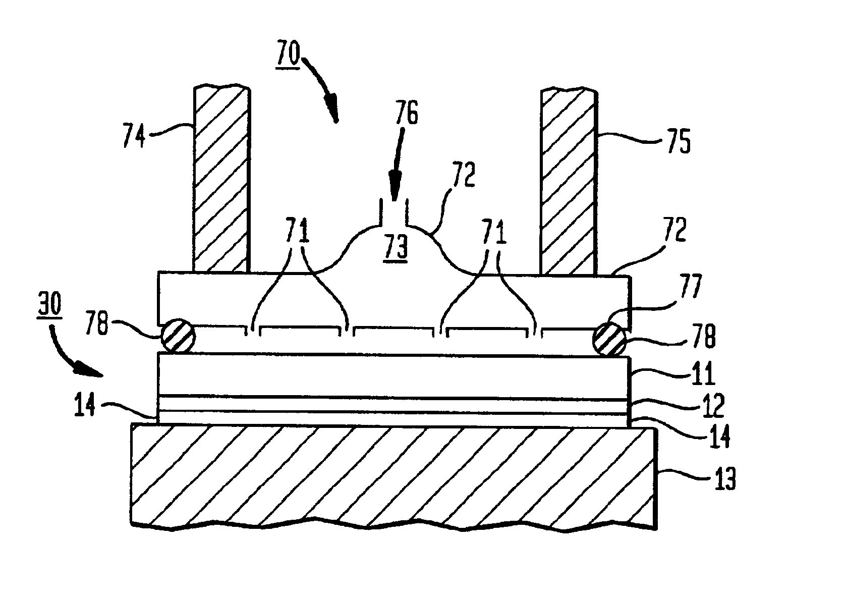
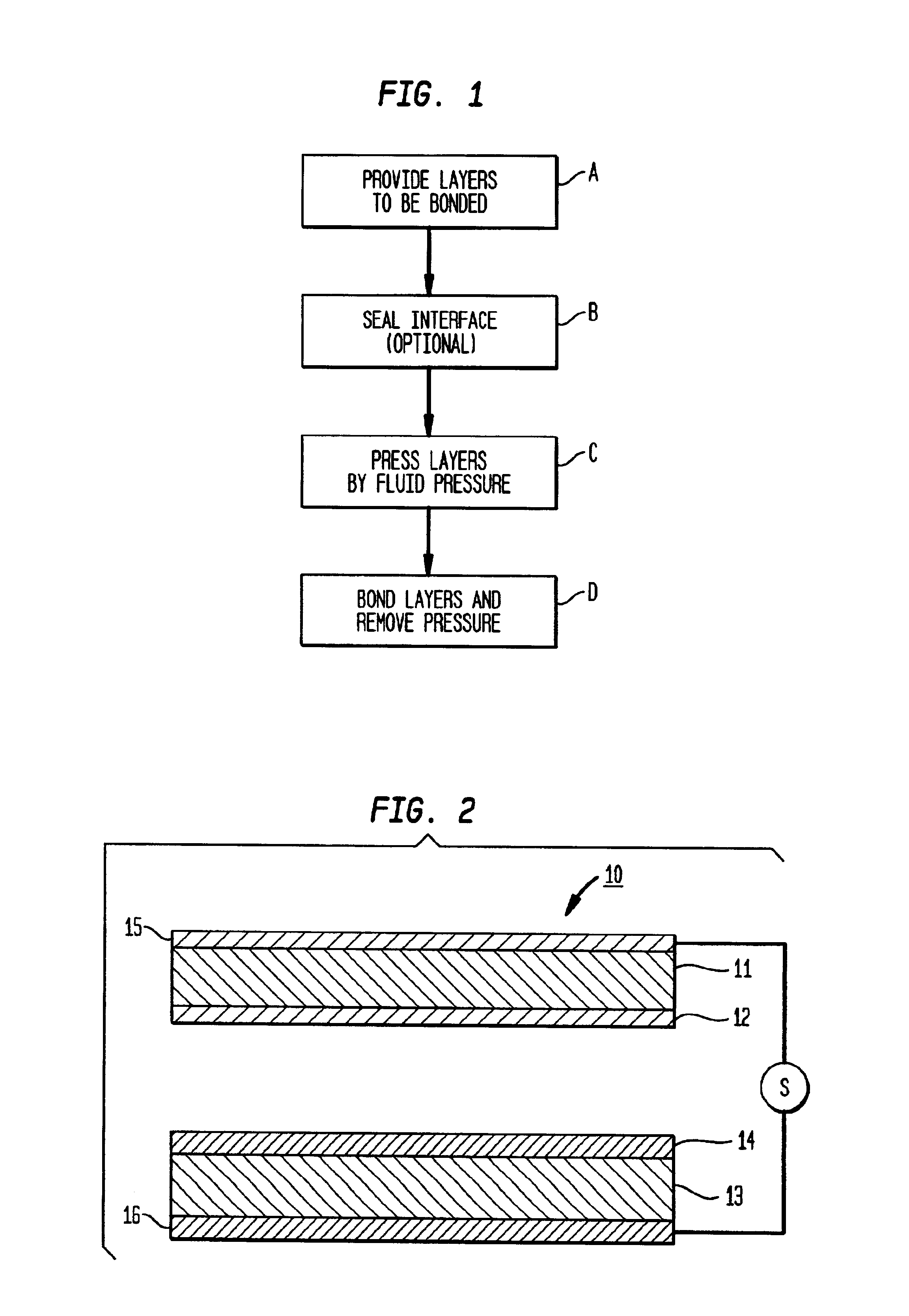
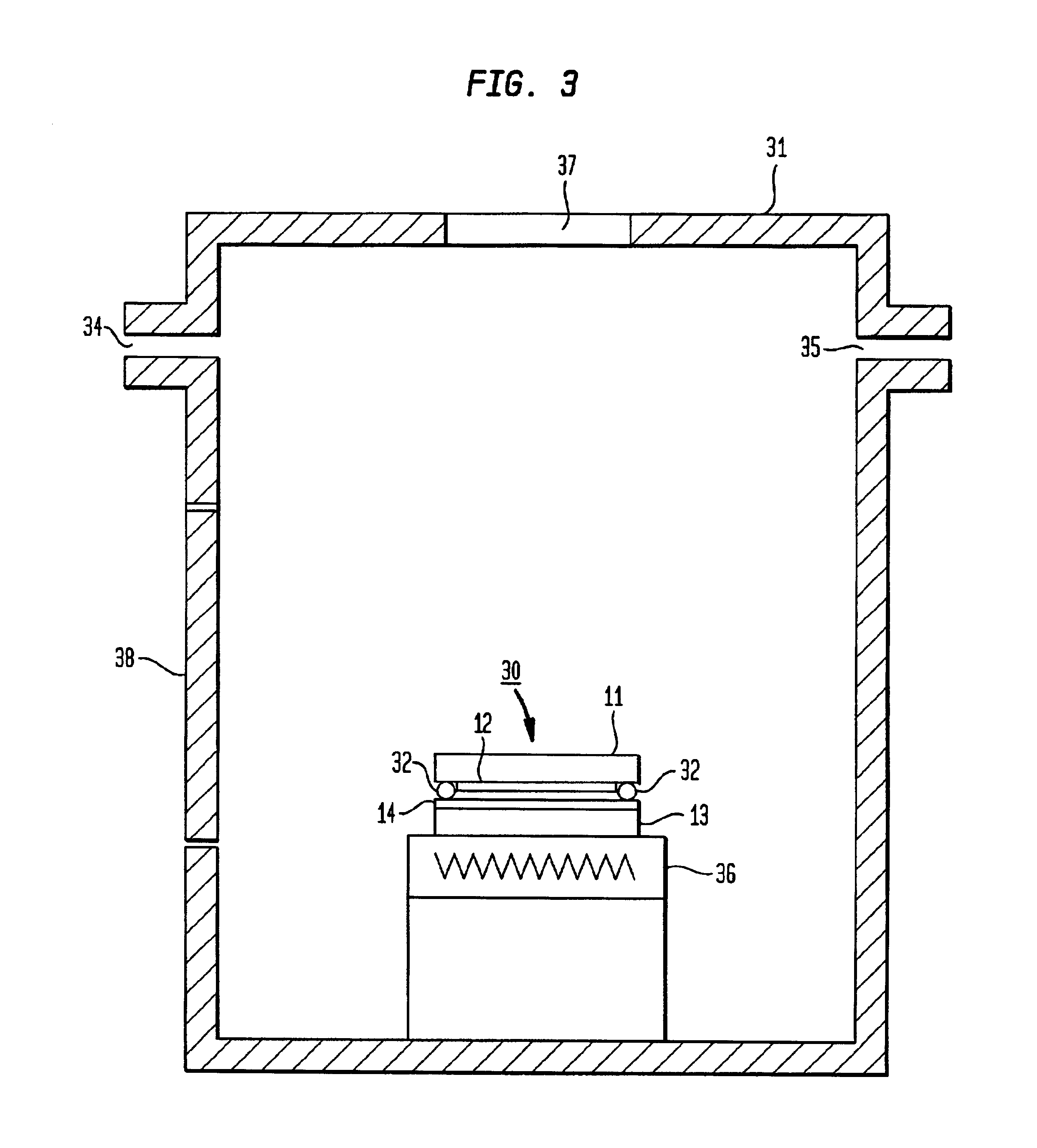
[0005]An improved method of bonding involves using direct fluid pressure to press together the layers to be bonded. Advantageously one or more of the layers are sufficiently flexible to provide wide area contact under the fluid pressure. Fluid pressing can be accomplished by sealing an assembly of layers to be bonded and disposing the assembly in a pressurized chamber. It can also be accomplished by subjecting the assembly to jets of pressurized fluid. The result of this fluid pressing is reduction of voids and enhanced uniformity over an enlarged area.

Problems solved by technology

This technique, however, has serious limitations in bonding layers of large area or imperfect planarity.
Even high precision mechanical presses present tolerance problems over large areas.
Presses move on guide shafts through apertures, and the spacings between the shafts and their respective apertures permit undesirable relative translational and rotational shifts between the assembly and the plates.
Thus mechanical presses present serious alignment problems in high precision bonding.
Moreover, despite the most careful construction, the layers to be bonded are not perfectly planar.
When assemblies of these layers are disposed on the rigid plates of a press, the deviations from planarity over large areas can result in variations in the bonding pressure and spacing.

Method used


Image

  • Fluid pressure bonding
  • Fluid pressure bonding
  • Fluid pressure bonding

Examples


Embodiment Construction

[0013]In accordance with the invention, the problem of unwanted lateral movements of mechanical presses in bonding is ameliorated by using direct fluid pressure to press together the layers to be bonded. The inventive method applies fluid pressure over the assembly of layers to be bonded. Because the fluid pressure is isostatic, no significant unbalanced lateral forces are applied. Direct fluid pressure also includes fluid pressure transmitted to the assembly via a flexible membrane, as the membrane does not interfere with the transmission of isostatic pressure from the fluid. And streaming pressurized fluid from openings in a pressure vessel can also apply nearly isostatic direct fluid pressure on the plates or assembly.

[0014]It is contemplated that the invention will have important applications in the bonding of previously patterned layers. The layers can be aligned with respect to previous patterns using conventional alignment techniques, and be pressed by direct fluid pressure t...


PUM

PropertyMeasurementUnit
thicknessaaaaaaaaaa
pressuresaaaaaaaaaa
areaaaaaaaaaaa

Abstract

An improved method of bonding involves using direct fluid pressure to press together the layers to be bonded. Advantageously one or more of the layers are sufficiently flexible to provide wide area contact under the fluid pressure. Fluid pressing can be accomplished by sealing an assembly of layers to be bonded and disposing the assembly in a pressurized chamber. It can also be accomplished by subjecting the assembly to jets of pressurized fluid. The result of this fluid pressing is reduction of voids and enhanced uniformity over an enlarged area.

Description

CROSS REFERENCES TO RELATED APPLICATIONS[0001]This application is a continuation-in-part of U.S. patent application Ser. No. 09 / 618,174 filed by Stephen Y. Chou on Jul. 18, 2000 now U.S. patent No. 6,482,742 and entitled “Fluid Pressure Imprint Lithography,” which application is incorporated herein by reference.FIELD OF THE INVENTION[0002]This invention relates to bonding and, in particular, to bonding wherein direct fluid pressure is used to press together a plurality of layers to be bonded. The process is particularly useful to provide void free, uniform bonding over an increased area. The bonding can be by pressure alone or by the application of pressure and heat or electrical field.BACKGROUND OF THE INVENTION[0003]Bonding is an important process in the fabrication of many industrial, electronic, biological and optical devices. Typically bonding is accompanied by pressure together with heat, electrical field or both heat and field. A plurality of layers to be bonded are stacked i...

Claims


Application Information

Patent Timeline
Patent Type & Authority Patents(United States)
IPC IPC(8): G03F7/00H01L51/40H01L51/05H01L21/027B29C59/02H10K99/00
CPCB29C43/003B29C43/021B82Y10/00B82Y40/00G03F7/0002B29C59/022B29C2043/025B29C2043/3233B29C2043/3238B29C2043/566B29C2059/023H01L51/0004Y10S438/945H10K71/13H01L21/027
Inventor CHOU
Owner NANONEX
Learn More