
Wireless engine monitoring system

a monitoring system and engine technology, applied in frequency-division multiplex details, special data processing applications, registration/indication of working vehicles, etc., can solve the problems of not giving analysts a complete picture of engine performance during flight, limited prior art techniques, reactive maintenance actions, etc., to increase engine “time on wing” and reduce engine maintenance costs.

Active Publication Date: 2005-09-13
HARRIS CORP
View PDF32 Cites 91 Cited by
  • Summary
  • Abstract
  • Description
  • Claims
  • Application Information

AI Technical Summary

Benefits of technology

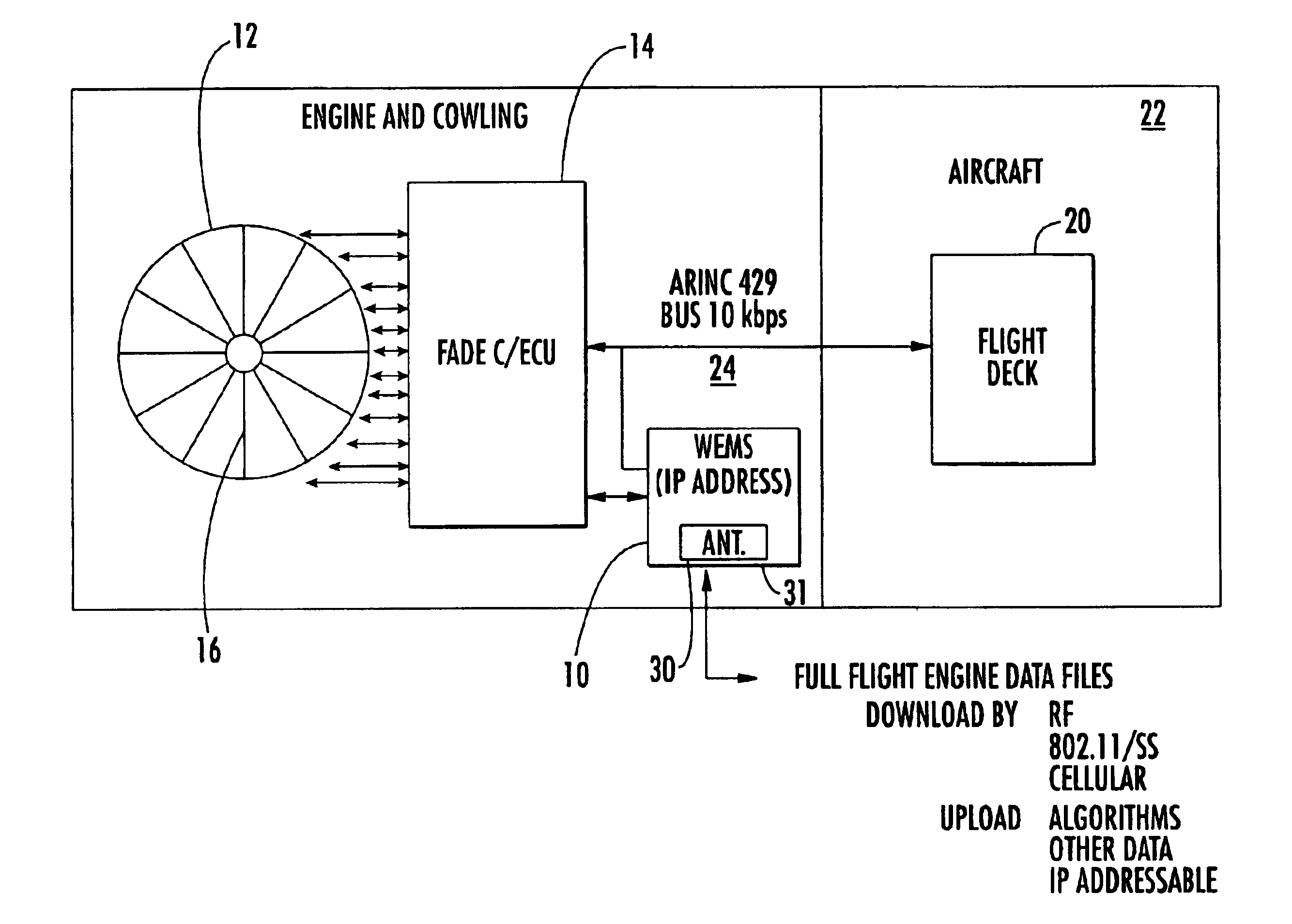
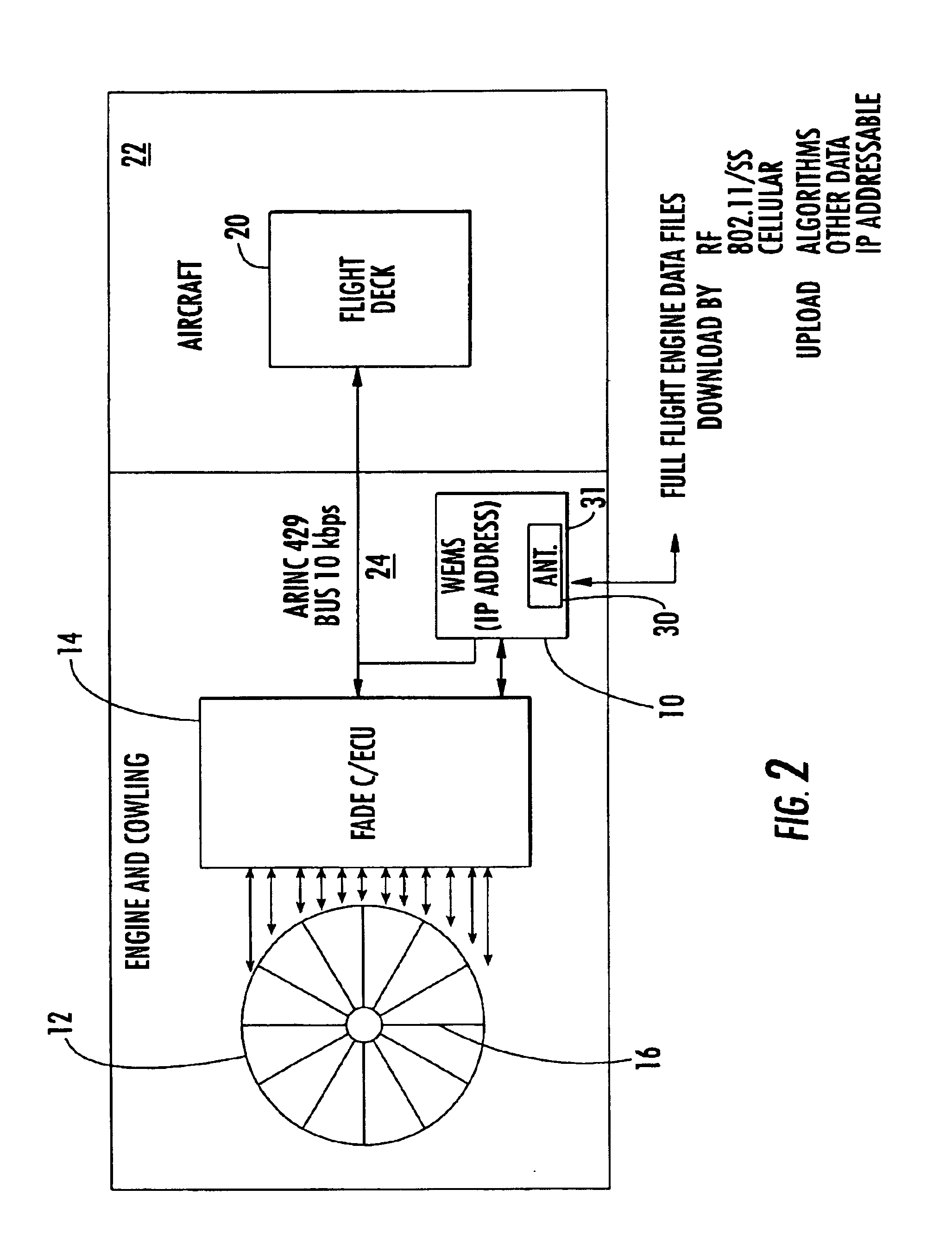
[0009]The “full flight” engine data allows advanced prognostics and diagnostics techniques and increases engine “time on wing” and decreases engine maintenance costs. The WEMS data could be downloaded via RF / (802.11) spread spectrum / cellular to an airport server for processing and / or transported over the internet, PSTN, cellular system or other communications network to another workstation for real-time analysis. Data can be uploaded to the wireless engine monitoring system module, including algorithms for on-board processing.

Problems solved by technology

Prior art techniques have been limited because of data latency and the limited amount of collected data restricted analysis.
Any resultant maintenance actions were reactive.
This data never gave analysts a complete picture of an engine performance during flight.
As a result, advanced prognostics and diagnostic techniques have not been used by prior art engine analysis systems.
Up to now, prior art systems were limited in their analysis to the prior art data “snapshots” and did not go beyond gross indicators and reactive maintenance techniques.
This engine data resulted in a limited engine analysis because only one “snapshot” of the engine performance had been used and the “snapshot” never gave a true indication of engine performance during flight of the aircraft.

Method used


Image

  • Wireless engine monitoring system
  • Wireless engine monitoring system
  • Wireless engine monitoring system

Examples


Embodiment Construction

[0022]The present invention will now be described more fully hereinafter with reference to the accompanying drawings, in which preferred embodiments of the invention are shown. This invention may, however, be embodied in many different forms and should not be construed as limited to the embodiments set forth herein. Rather, these embodiments are provided so that this disclosure will be thorough and complete, and will fully convey the scope of the invention to those skilled in the art. Like numbers refer to like elements throughout, and prime notation is used to indicate similar elements in alternative embodiments.

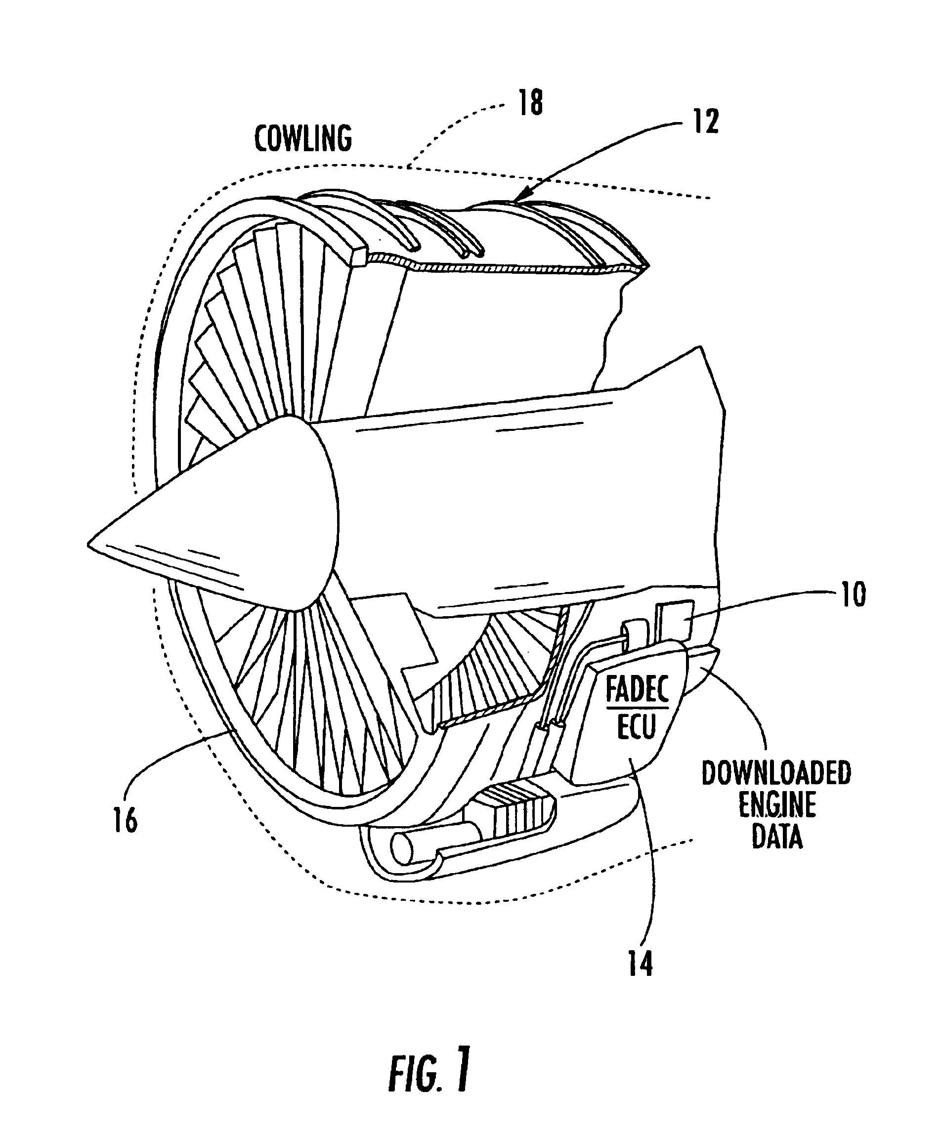
[0023]The present invention is a wireless engine monitoring system (WEMS) and can use basic components of the ground data link unit as disclosed in the incorporated by reference '165, '179 and '734 patents. The system of the present invention is reduced in function and size for a WEMS module and is mounted directly to the jet engine and preferably interfaces with the FADEC / ...


PUM


Abstract

A wireless engine monitoring system (WEMS) includes an engine monitoring module that is mounted directly on an aircraft engine and records, stores, encrypts and transmits full flight engine data. The system preferably interfaces to the Full Authority Digital Engine Controller / Engine Control Unit (FADEC / ECU) and can record hundreds of engine parameters with a preferred sampling frequency of about one second. The engine monitoring module is preferably formed as a miniaturized module directly mounted on the aircraft engine within its cowling and has a conformal antenna. The engine monitoring module can also upload data for onboard processing.

Description

RELATED APPLICATION[0001]This application is based upon prior filed provisional application Ser. No. 60 / 489,368 filed Jul. 23, 2003.FIELD OF THE INVENTION[0002]The present invention relates to a system and method for monitoring aircraft engines, and more particularly, this invention relates to a system and method for determining an aircraft engine's current performance and downloading data for each engine of an aircraft and processing the engine data for engine maintenance and other analysis.BACKGROUND OF THE INVENTION[0003]The Federal Aviation Administration and other international aviation regulatory agencies require commercial airlines to monitor the health and status of aircraft engines. Any health and status information is used to determine the current performance for an aircraft engine and determine if maintenance is required. Prior art techniques have been limited because of data latency and the limited amount of collected data restricted analysis. Typically, gross indicators...

Claims


Application Information

Patent Timeline
Patent Type & Authority Patents(United States)
IPC IPC(8): G05B23/02
CPCB64D29/00F02C9/00G05B23/0213G05B23/0264H04B7/18506B64D2045/0085G05B2219/13Y02T50/67Y02T50/672G05B2223/06Y02T50/60G01M15/14G07C5/008G07C5/0808G07C5/0816G08C17/02G01R31/008Y02T10/40Y10S123/00B64D45/00H04L67/12
Inventor ZIARNO, JAMES J.
Owner HARRIS CORP
Learn More