
Voltage controlled oscillator and electronic system using the same

a voltage control and oscillator technology, applied in the direction of pulse generator, pulse generation by vacuum tubes, pulse technique, etc., can solve the problem of limited frequency output rang

Inactive Publication Date: 2005-09-13
INNOLUX CORP
View PDF3 Cites 4 Cited by
  • Summary
  • Abstract
  • Description
  • Claims
  • Application Information

AI Technical Summary

Benefits of technology

[0011]Accordingly, the voltage controlled oscillator provided by the present invention output higher frequency when the input voltage becomes higher.

Problems solved by technology

However, the conventional voltage control oscillator 10 has the following problems.
Therefore, the output range of the frequency is limited.

Method used


Image

  • Voltage controlled oscillator and electronic system using the same
  • Voltage controlled oscillator and electronic system using the same

Examples


Embodiment Construction

[0017]Reference will now be made in detail to the present preferred embodiments of this invention, examples of which are illustrated in the accompanying drawings. Wherever possible, the same reference numbers are used in the drawings and the description to refer to the same or like parts.

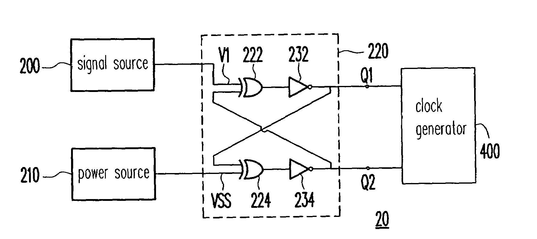
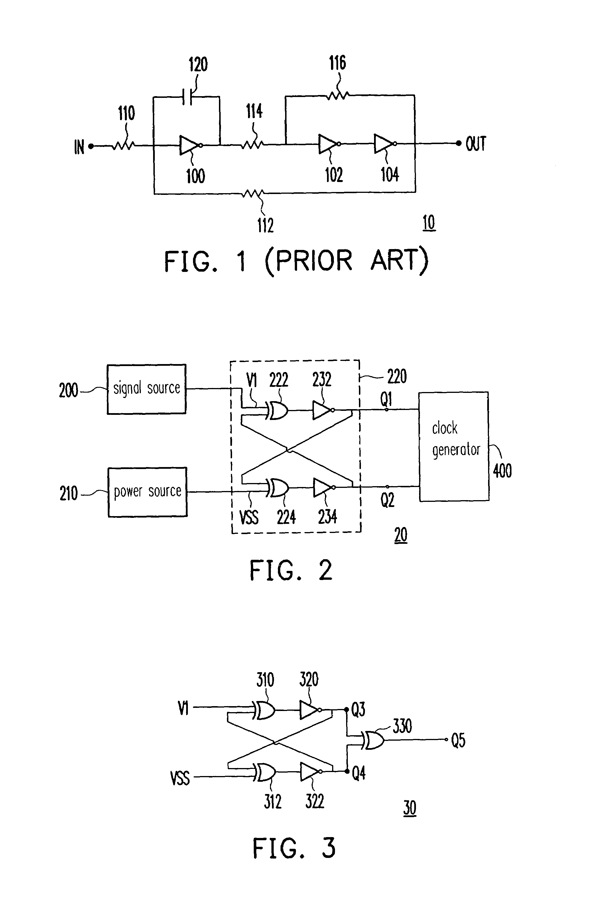
[0018]Referring to FIG. 2, which is a block diagram of an electronic system with a voltage controlled oscillator according to an embodiment of the present invention. In this embodiment, the electronic system 20 includes a signal source 200, a power source 210 and a voltage controlled oscillator (VCO) 220, as well as a clock generator 400 for example. The signal source 200 provides a signal V1 to the VCO 220 while the power source 210 provides a reference voltage VSS to the VCO 220. The VCO 220 includes two XOR logic units 222, 224 and two inverters 232, 234. The XOR logic unit 222 receives the signal V1 and the output signal Q2, performs an XOR logic operation based on these data and generates a fir...


PUM


Abstract

A voltage controlled oscillator comprises two XOR logic units and two inverters. A first inverter inverts a first XOR result into a first output signal; a second inverter inverts a second XOR result into a second output signal; a first XOR logic unit performs an XOR logic operation based on an input signal and the second output signal and thus generating the first XOR result; and a second XOR logic unit performs an XOR logic operation based on the first output signal and a reference voltage and thus generates the second XOR result.

Description

BACKGROUND OF THE INVENTION[0001]1. Field of Invention[0002]The present invention relates to a voltage controlled oscillator. More particularly, the present invention relates to a voltage controlled oscillator employing XOR logic unit, and electronic system using the same.[0003]2. Description of Related Art[0004]The construction of a conventional voltage controlled oscillator is explained referring to FIG. 1. Generally, a voltage control oscillator (VCO) 10 has a plurality of inverters 100, 102 and 104, which are connected in series, a plurality of resistors 110, 112, 114 and 116, and a capacitor 120. A supply voltage VDD (which is not shown) applied to the inverters 100, 102 and 104 makes the inverters 100, 102 and 104 output signals in response to voltage inputs to respective inverters, wherein the respective output signals are either input to downstream inverters or output of the VCO 10 as the case may be.[0005]However, the conventional voltage control oscillator 10 has the follo...

Claims


Application Information

Patent Timeline
IPC IPC(8): H03B5/00H03B5/20H03B5/24
CPCH03K3/03
Inventor LI, YAN-LIANG
Owner INNOLUX CORP
Learn More