
Oscillation detection circuit

a detection circuit and oscillator technology, applied in the direction of generating/distributing signals, instruments, pulse techniques, etc., can solve the problems of low discharge value, undesired situation, and reduced yield in circuit production, so as to avoid the occurrence of glitches in detection signals and eliminate ripples in signals

Inactive Publication Date: 2005-09-13
YAMAHA CORP
View PDF6 Cites 6 Cited by
  • Summary
  • Abstract
  • Description
  • Claims
  • Application Information

AI Technical Summary

Benefits of technology

[0024]It is an object of the invention to provide an oscillation detection circuit that can detect an oscillation mode of an oscillation circuit in a stable manner without being badly affected by dispersions of characteristics of transistors.
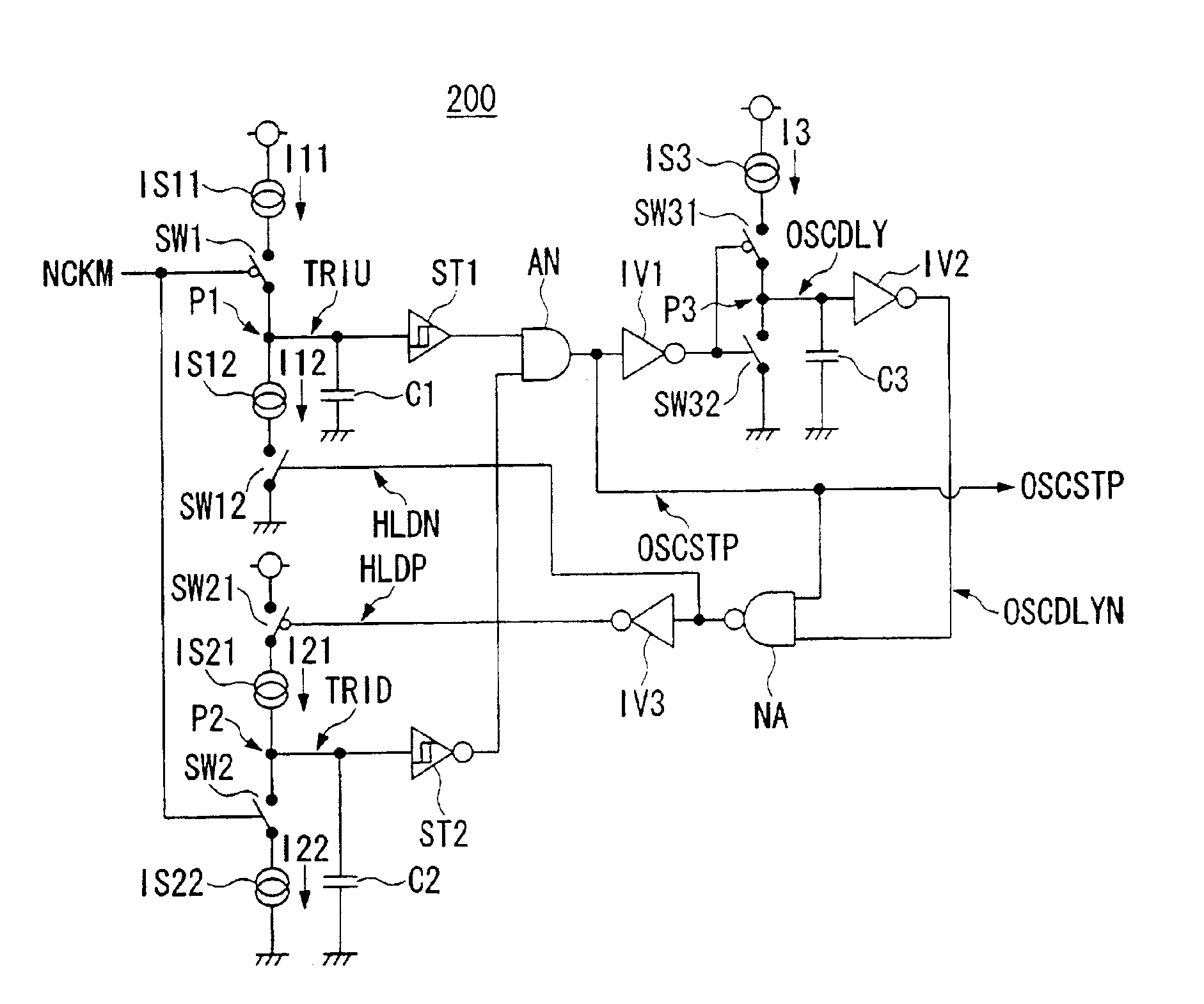
[0026]In the above, it is possible to additionally arrange a current breaking circuit for temporarily making the first current source or the second current source inoperable as necessary, whereby it is possible to completely eliminate ripple contained in the signal at the connection point, thus avoiding occurrence of glitch in the detection signal.

Problems solved by technology

Otherwise, the oscillation detection circuit may have difficulties in detecting oscillation, which may cause a reduction of yield in production of circuits.
However, if the delay time of the delay circuit DL is greatly varied or if the time constants are greatly varied due to dispersions of on-resistances of transistors constituting the exclusive-or circuit EO, there may occur an undesired situation where the discharged value does not exceed the charged value.
This makes oscillation detection inoperable, which may cause a reduction of yield in production of circuits.
The aforementioned oscillation detection circuit of FIG. 8A may have a similar problem, wherein both the signals INA and INB are not simultaneously placed in a low level due to unexpected dispersions of on-resistances of transistors constituting the inverters INA to INC, in other words, either one of the signals INA and INB may be unexpectedly placed in a high level.
This makes oscillation detection inoperable.

Method used


Image

  • Oscillation detection circuit
  • Oscillation detection circuit
  • Oscillation detection circuit

Examples


first embodiment

1. First Embodiment

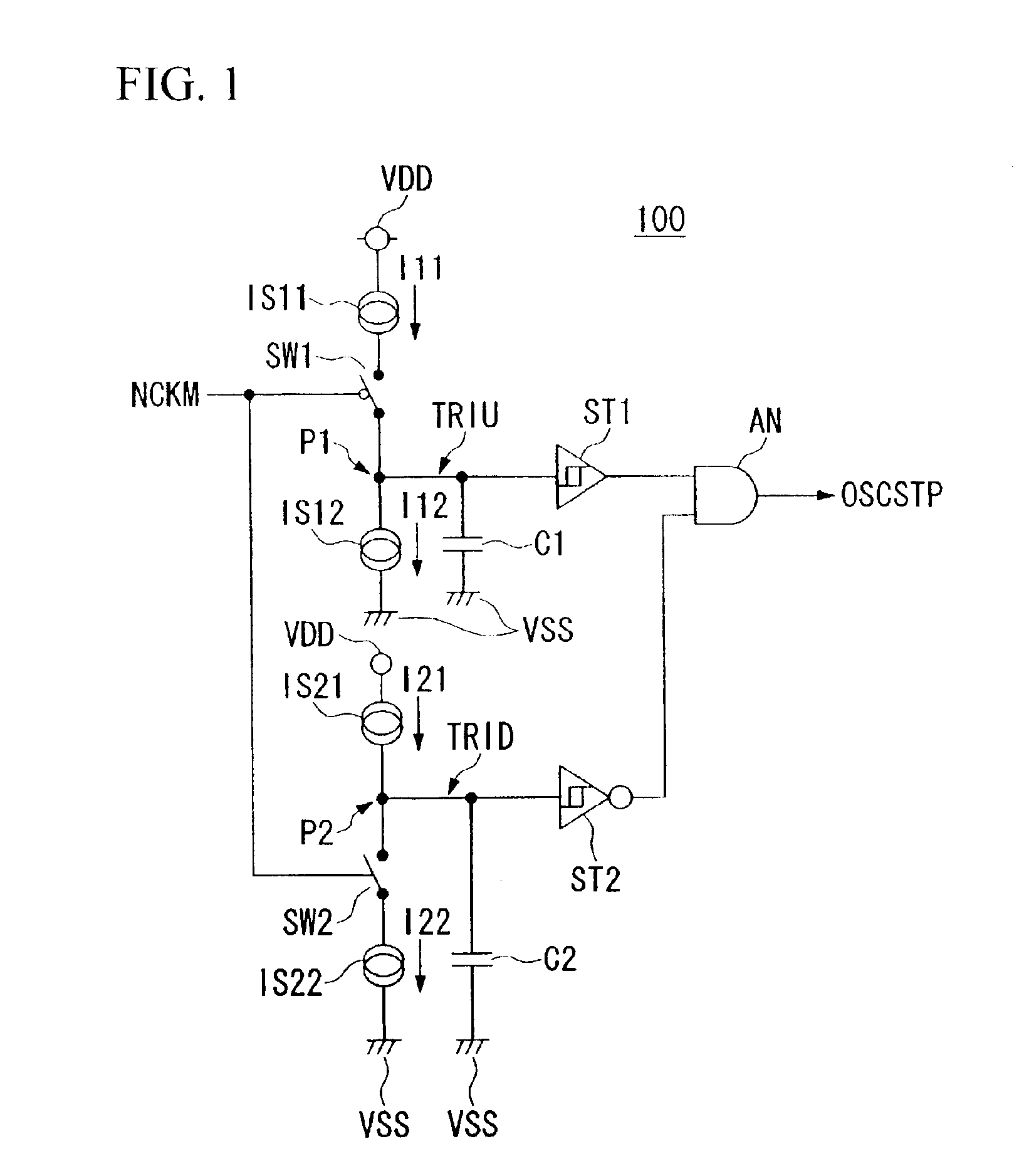
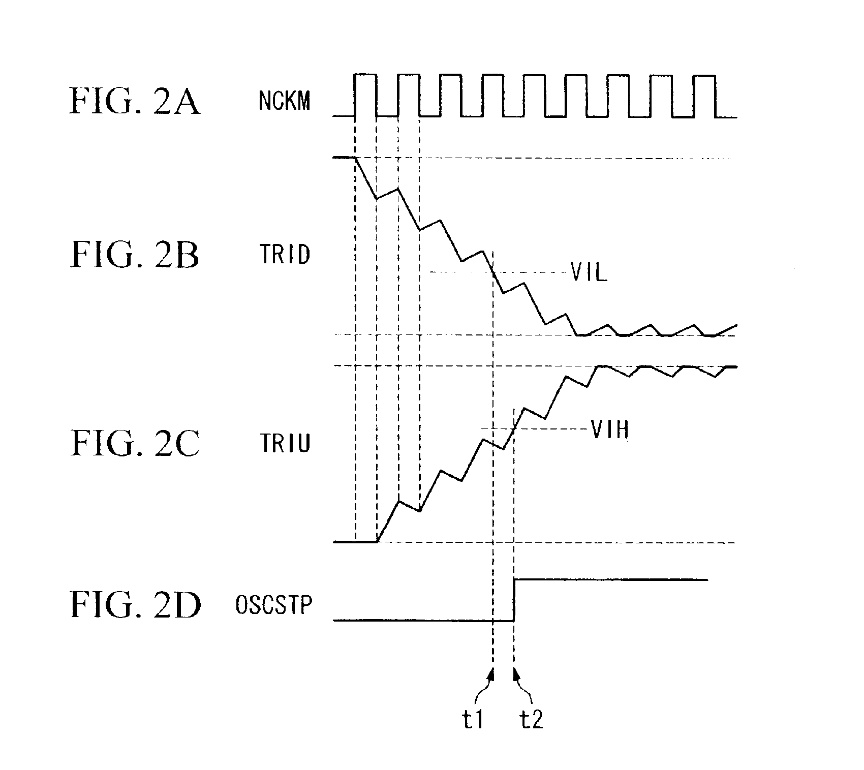
[0061]FIG. 1 shows the configuration of an oscillation detection circuit in accordance with a first embodiment of the invention. That is, an oscillation detection circuit 100 of FIG. 1 is designed to detect oscillation (or an oscillation mode) of an oscillation circuit (not shown), wherein a capacitor is repeatedly charged and discharged by a current source producing a relatively large current that is turned on and off based on an oscillation signal, while another capacitor is repeatedly charged and discharged by a current source producing a relatively small current.

[0062]In FIG. 1, a current source IS11 and a current source IS12 are connected in series between a voltage source (or a supply voltage) VDD and a ground potential VSS, wherein they differ from each other in current values, that is, the current value of the current source IS11 is set greater than the current value of the current source IS12. While satisfying such a relationship between the current value...

second embodiment

2. Second Embodiment

[0079]Next, an oscillation detection circuit of a second embodiment of the invention will be described in detail, wherein the second embodiment is designed to eliminate a minor drawback of the first embodiment. Therefore, before describing the second embodiment, a description will be given with respect to the minor drawback of the first embodiment.

[0080]In the first embodiment shown in FIG. 1, ripples may occur in the signals TRIU and TRID, emerged at the connection points P1 and P2, due to repetition of open and closed states of the switches SW1 and SW2. Normally, ripples may be eliminated or absorbed by hysteresis characteristics of the Schmitt triggers ST1 and ST2, so that the detection signal OSCSTP would not be affected by ripples.

[0081]However, when ripples of the signals TRIU and TRID become apparent beyond absorbing capacities based on hysteresis characteristics of the Schmitt triggers ST1 and ST2, glitch may occur in the detection signal OSCSTP. For exam...


PUM


Abstract

An oscillation detection circuit is constituted by at least one circuitry comprising a first current source for charging a capacitor and a second current source for discharging the capacitor, which are connected in series via a switch controlled to be opened or closed in response to an output signal of an oscillation circuit, wherein the first current source is greater than the second current source in current value. Herein, a signal emerging at a connection point of the first and second current sources is integrated as the switch is repeatedly turned on and off in response to the oscillation signal whose level is periodically changed in an oscillation mode. A Schmitt trigger is arranged to produce a detection signal based on the signal at the connection point between the first and second current sources.

Description

BACKGROUND OF THE INVENTION[0001]1. Field of the Invention[0002]This invention relates to oscillation detection circuits for detecting oscillations of oscillation circuits such as crystal oscillators, and in particular relates to oscillation detection circuits for avoiding operation errors due to dispersions and variations of circuit constants of oscillation circuits.[0003]2. Description of the Related Art[0004]Conventionally, oscillation circuits are installed in electronic devices to produce oscillation signals, based on which electronic circuits operate. In order to guarantee operations of circuitry inputting output signals of oscillation circuits, it is necessary to detect whether or not oscillation circuits are placed in oscillated states. Therefore, oscillation detection circuits are conventionally used, and various examples of oscillation detection circuits using delay circuits have been disclosed in Japanese Unexamined Patent Publication No. Hei 10-190413, Japanese Unexamine...

Claims


Application Information

Patent Timeline
Patent Type & Authority Patents(United States)
IPC IPC(8): H03K4/02H03K5/19H03K4/00H03B1/00H03K3/02H03L3/00
CPCH03K5/19H03L3/00
Inventor SEKIMOTO, YASUHIKO
Owner YAMAHA CORP
Learn More