
Photographic processing system having a vertical stacker arrangement

a technology of photographic processing and stacking, which is applied in the direction of printers, instruments, photosensitive materials, etc., can solve the problems of not ensuring the flatness of the photographic media, the use of conveying rollers, etc., and achieve the required amount of developing time and high speed processing. , the effect of high speed

Inactive Publication Date: 2005-09-13
EASTMAN KODAK CO
View PDF4 Cites 1 Cited by
  • Summary
  • Abstract
  • Description
  • Claims
  • Application Information

AI Technical Summary

Benefits of technology

The present invention provides a photographic processing system and method that combines a stacker / dryer arrangement and a vacuum platen to achieve high-speed processing. The system is designed to provide enough dwell time for the media in the stacker arrangement to ensure adequate processing. The method involves feeding media, exposing it, applying developer, and delivering it to a vertical stacker arrangement for the desired developing time. The media is then pushed through a stop solution and onto a valve jet bleaching platen for the proper amount of bleach. It is then delivered to another stacker arrangement for the proper amount of bleach time, and finally to a wash station for the proper amount of washing. The media is then delivered back to the first stacker arrangement for final drying and delivery to the exit side of the processing machine. The invention also includes a first solution application station, a first vertical stacker arrangement, a second solution application station, and a second vertical stacker arrangement for sequential processing of photographic media with different solutions. The technical effects of the invention include high-speed processing, efficient use of solution, and improved quality of photographic media.

Problems solved by technology

Further, the utilization of conveying rollers in most instances does not insure that the photographic media is held flat during the processing cycle.

Method used


Image

  • Photographic processing system having a vertical stacker arrangement
  • Photographic processing system having a vertical stacker arrangement
  • Photographic processing system having a vertical stacker arrangement

Examples


Embodiment Construction

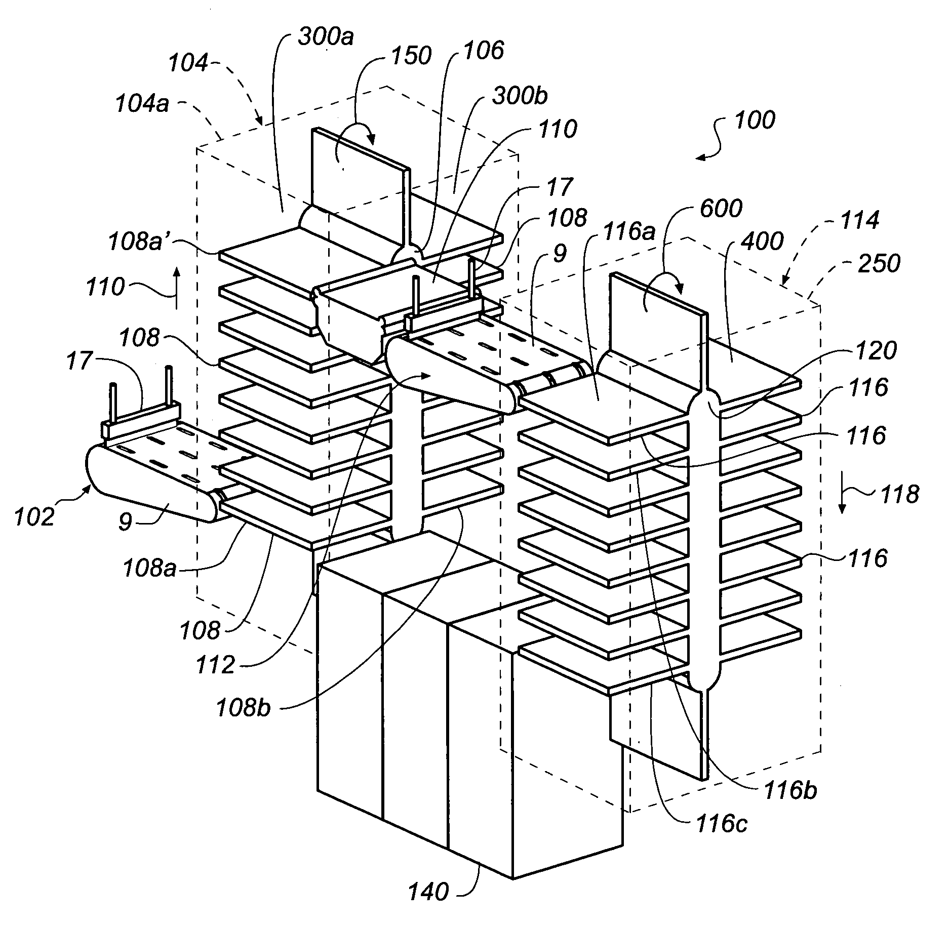
[0010]Referring now to the drawings, wherein like reference numeral designate identical or corresponding parts throughout the several views, FIG. 1 is a schematic illustration of a photographic processor 100 in accordance with the present invention.

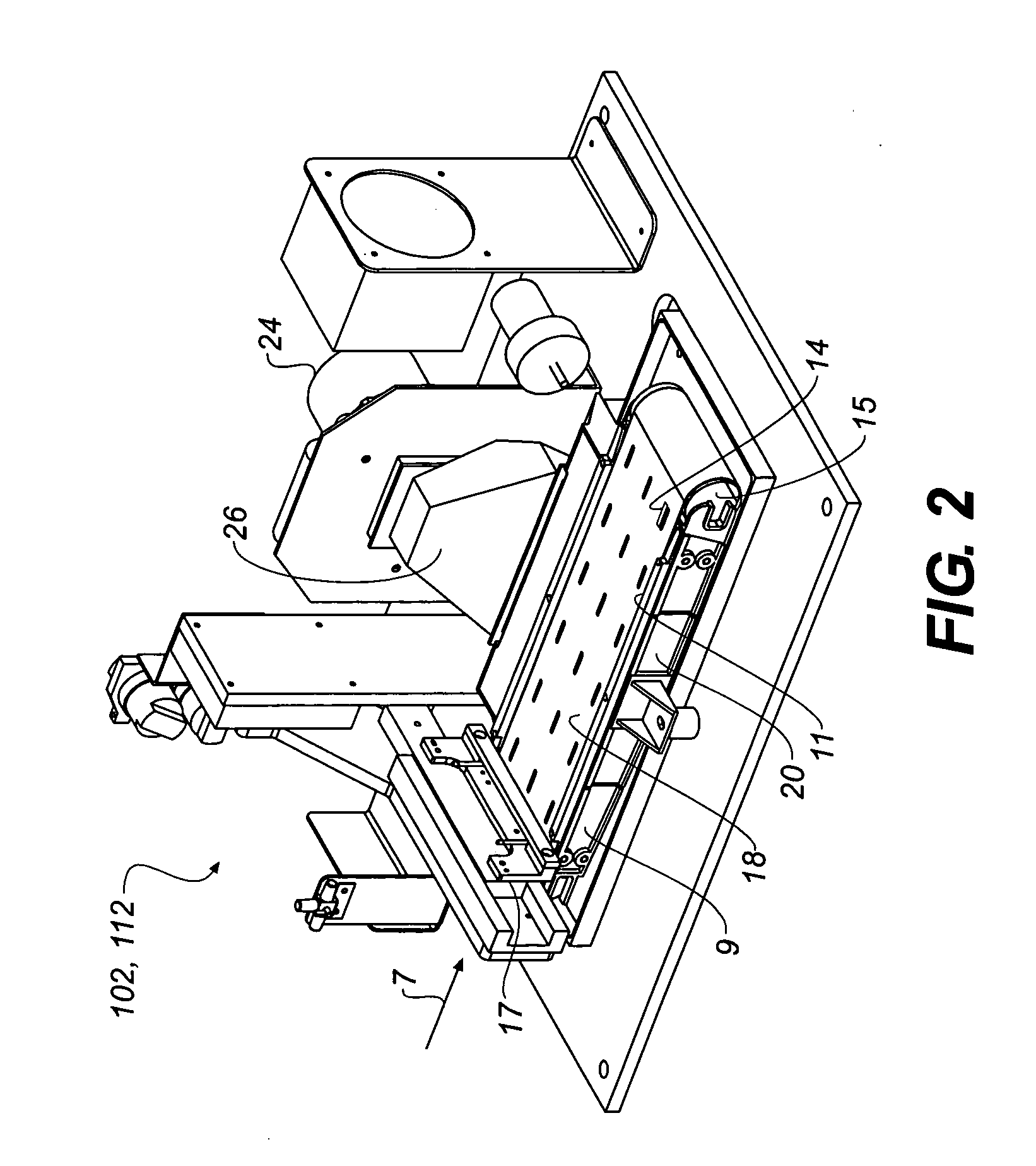
[0011]Photographic processor 100 of FIG. 1 is adapted to process sheets of exposed photographic material. In photographic processor 100, a sheet of exposed photographic material is first conveyed to a first solution application station 102. First solution application station 102 includes a first solution supply member 17 which is adapted to supply a first processing solution onto the photographic media as the photographic media passes between first solution supply member 17 and a conveying path defined by a conveying member 9. Conveying member 9 is preferably of a vacuum platen type as described in copending application Ser. No. 10 / 714,008 filed Nov. 14, 2003. With reference to the specifics of first solution application station 102, refe...


PUM

PropertyMeasurementUnit
travel timeaaaaaaaaaa
timeaaaaaaaaaa
vacuum suction forceaaaaaaaaaa

Abstract

The invention relates to a photographic processor and a method of processing photographic material. The photographic processor is adapted to achieve a high speed processing of photographic material by utilizing the combination of a vacuum platen and a stacker arrangement that is adapted to hold the media for a time necessary to process and / or dry the media. The system permits media to be fed to a first vacuum platen where a first solution is applied. The platen transports the media to a first vertical stacker arrangement, which holds the media for a desired processing time for the first solution. The media can then be pushed through a stop solution, if needed, and onto a second vacuum platen where a second solution can be applied. The media is then delivered to second vertical stacker arrangement that is designed to assure the proper amount of processing time for the second solution.

Description

FIELD OF THE INVENTION[0001]The present invention relates to a photographic processing system which is adapted to achieve a high speed processing utilizing a stacker / drying arrangement.BACKGROUND OF THE INVENTION[0002]Conventional photographic systems for processing photographic material generally process the media in processing tanks, wherein the media is conveyed through the tanks so as to be in contact with several distinct processing solutions in each tank. The conveyance of the media essentially utilizes conveying rollers which in most instances touch both the emulsion and non-emulsion side of the photographic media. Further, the utilization of conveying rollers in most instances does not insure that the photographic media is held flat during the processing cycle. These factors generally affect the subsequent processing of the photographic media. Conventional photographic systems are also set forth in an in-line relationship that includes a plurality of processing tanks and a d...

Claims


Application Information

Patent Timeline
Patent Type & Authority Patents(United States)
IPC IPC(8): G03C3/00G03D5/00G03D3/08G03D5/04
CPCG03D5/04
Inventor PICCININO, JR., RALPH L.PAGANO, DANIEL M.
Owner EASTMAN KODAK CO
Learn More