
Photographic processing apparatus for photosensitive material

a technology of photosensitive materials and processing equipment, which is applied in the direction of photosensitive materials, drying machines with progressive movements, furnaces, etc., can solve the problems of wasteful power use and high electric energy requirements

Inactive Publication Date: 2004-03-16
FUJIFILM CORP +1
View PDF1 Cites 3 Cited by
  • Summary
  • Abstract
  • Description
  • Claims
  • Application Information

AI Technical Summary

Benefits of technology

The present invention relates to a photographic processing apparatus for photosensitive material. The technical effect of this invention is to provide a photographic processing apparatus that can efficiently dry photosensitive material while saving energy. The apparatus includes a drier that uses heat to dry the material, but the heat is only applied when the material reaches the drier, which can result in a delay and wastes power. To address this problem, the invention includes a controller that synchronizes the heating of the drier with the arrival of the material, so that the material is heated just as it passes through the predetermined travel path. This reduces the time required for the material to reach the target temperature and ensures that the heat is only applied when necessary. Additionally, the invention includes a temperature sensor to measure the initial temperature of the air in the drier, which helps the controller to estimate the expected warmup time and start the heating at the right time. Overall, this invention provides a more efficient and energy-saving photographic processing apparatus for photosensitive material.

Problems solved by technology

However, a considerably high electric energy is required to raise the air temperature of the drier to a target temperature before the time of reach of the photographic paper to the drier after outputting of an image output signal for printing to the photographic paper.
In the prior art, the drier is kept at a constant high temperature by preheating operation, which causes wasteful use of power.

Method used


Image

  • Photographic processing apparatus for photosensitive material
  • Photographic processing apparatus for photosensitive material
  • Photographic processing apparatus for photosensitive material

Examples


Embodiment Construction

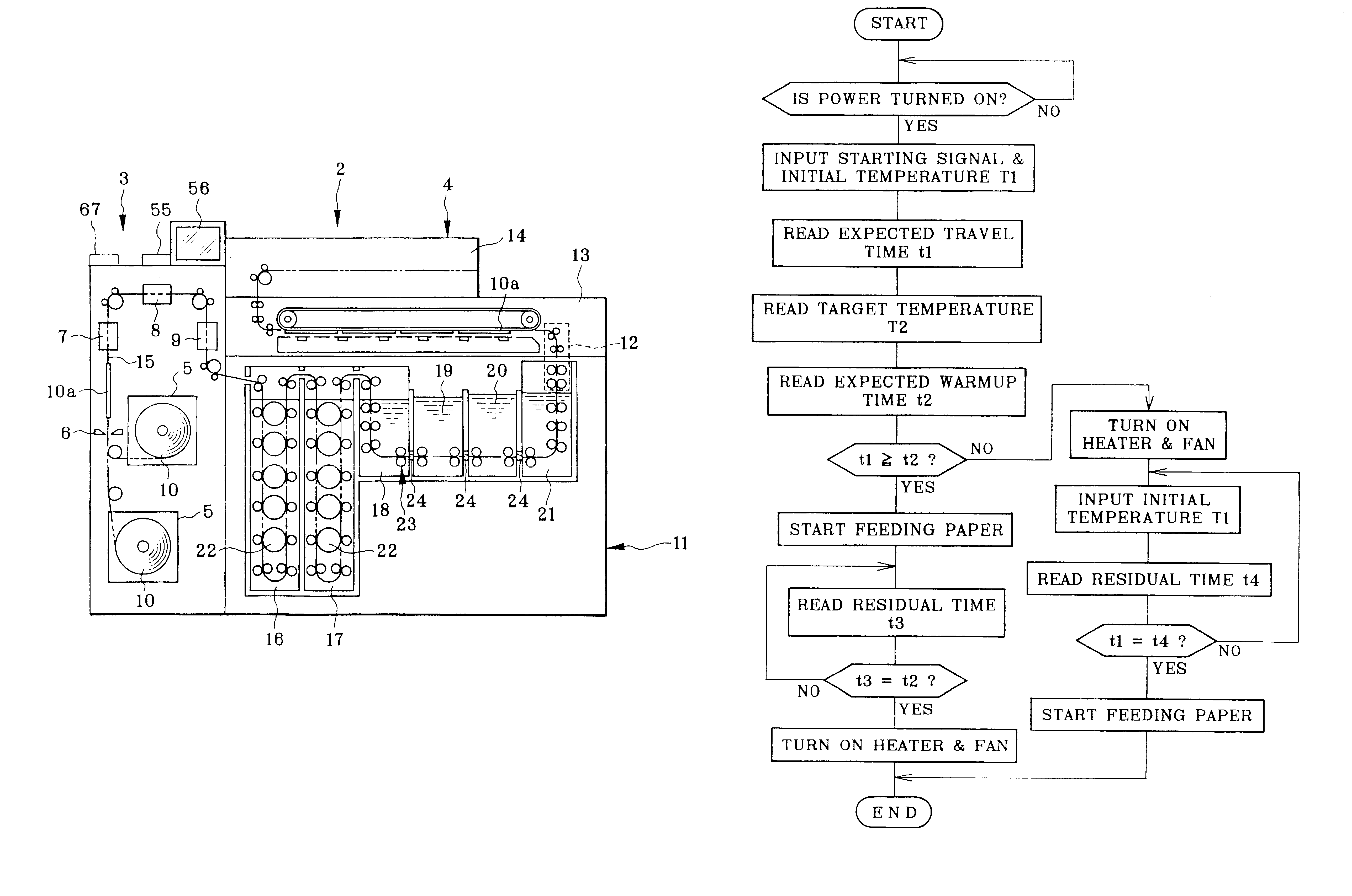
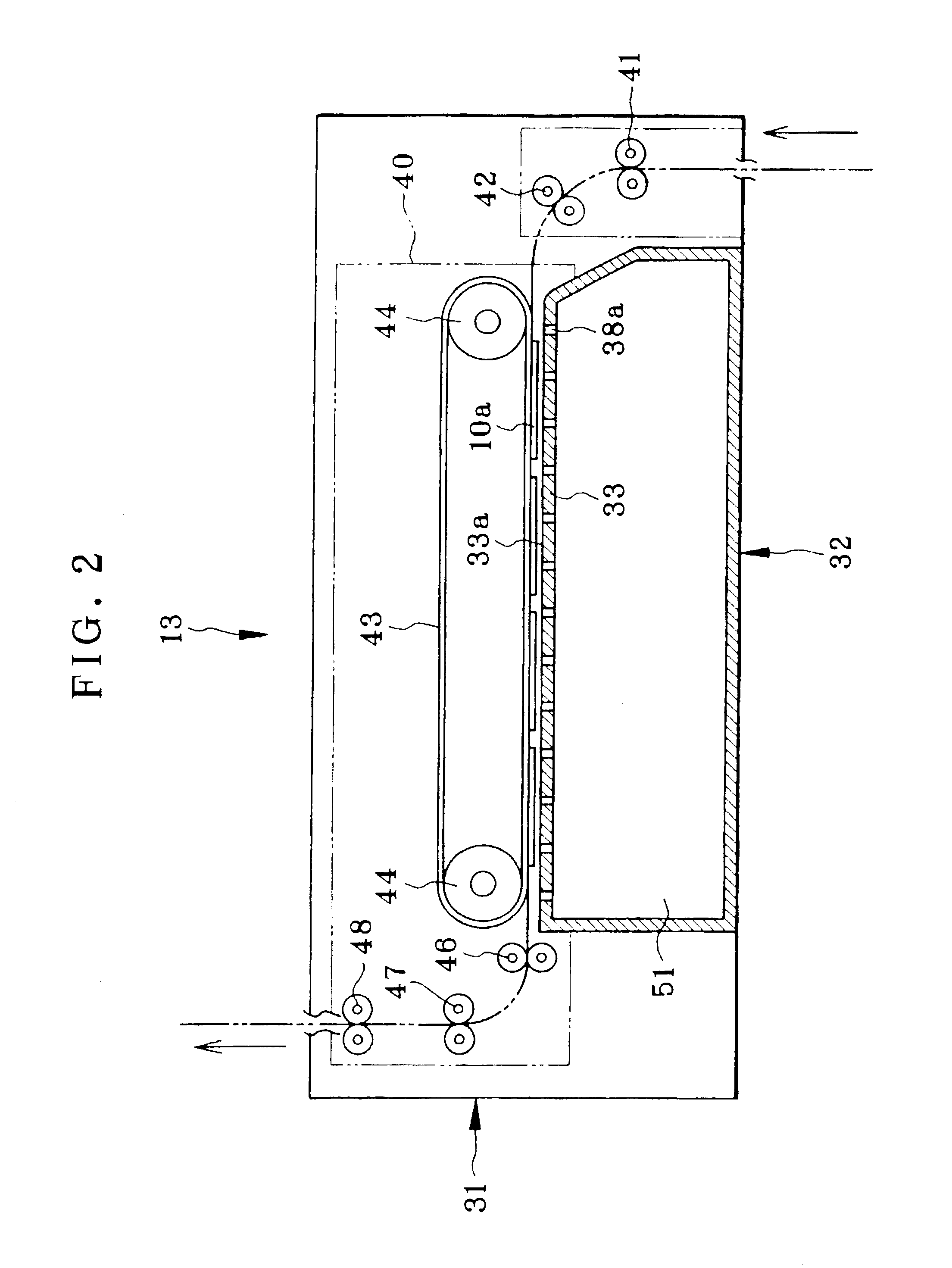
In FIG. 1, an inner structure of a printer / processor 2 is illustrated. The printer / processor 2 is a combined apparatus including a printer section 3 and a processor section 4. The printer section 3 is loaded with a paper supply magazine 5 as material supply position, and is constituted by a cutter 6, a back imprinting unit 7, an exposure unit 8 and a sorter 9. Long photographic paper 10 as photosensitive material is set in the paper supply magazine 5, and cut by the cutter 6 according to a printing size, to obtain a photographic paper sheet 10a. There is a travel path 15 indicated by the phantom line in FIG. 1, for feeding the paper sheet 10a toward the exposure unit 8. In the feeding, the back imprinting unit 7 imprints information to a back surface of the paper sheet 10a, the information including a frame number, correction data and the like. The exposure unit 8 prints an image to a print surface of the paper sheet 10a by exposure according to image data. The paper sheet 10a is al...


PUM


Abstract

A photographic processing apparatus includes a photographic paper processing bath train. A drier, positioned downstream from the train, heats air and dries the photographic paper. Feeding racks feed the paper in a predetermined travel path which begins on an upstream side of the train, extends therethrough, and ends at the drier. A memory is accessed to estimate expected travel time t1 for passing of the paper through the travel path. The memory is accessed to estimate expected warmup time t2 for warming up the air in the drier to a target temperature T2. A controller compares the time t1 and the time t2, initially starts heating in the drier if the time t2 is longer than the time t1, and starts actuation of the feeding racks when a time difference (t2-t1) elapses after start of the heating to synchronize drier warmup to temperature T2 with paper reaching the drier.

Description

1. Field of the InventionThe present invention relates to a photographic processing apparatus for photosensitive material. More particularly, the present invention relates to a photographic processing apparatus for photosensitive material in which a drier dries the photosensitive material by applying heat, and an energy saving operation is possible even in generating the heat.2. Description Related to the Prior ArtA printer / processor is an apparatus used in a photo laboratory, and in which a printer section and a processor section are combined in a single manner. Photographic paper as photosensitive material is set in a paper magazine, cut by a cutter according to a printing size into a paper sheet. The paper sheet is subjected to exposure for printing in an exposure unit, to record an image photographically in a form of a latent image. The photographic paper after the exposure is aligned in one train or sorted into plural trains by a sorter, and is fed to a processor section. As is...

Claims


Application Information

Patent Timeline
Patent Type & Authority Patents(United States)
IPC IPC(8): G03D15/02G03D3/00
CPCG03D15/022
Inventor YOSHIDA, FUTOSHISEGUCHI, YOSHINORI
Owner FUJIFILM CORP
Learn More