
Resonator for active noise attenuation system

a technology of active noise attenuation and resonance, which is applied in the field of resonance, can solve the problems of low frequency engine noise and attenuated engine noise level, and achieve the effect of reducing low frequency engine noise and less vehicle electrical power

Inactive Publication Date: 2005-09-06
3840620 CANADA
View PDF9 Cites 8 Cited by
  • Summary
  • Abstract
  • Description
  • Claims
  • Application Information

AI Technical Summary

Benefits of technology

"The patent describes an active noise attenuation system for reducing low-frequency engine noise in vehicles. The system includes an air inlet duct housing with a resonator that attenuates the noise, a sound detector, and a speaker assembly. The system also uses a controller to phase shift the noise signal and send it to the speaker to create a sound field that cancels out the remaining engine noise. An air filter is installed within the housing to filter out contaminants from the air flow. The system reduces low-frequency engine noise by using smaller speakers and less vehicle electrical power."

Problems solved by technology

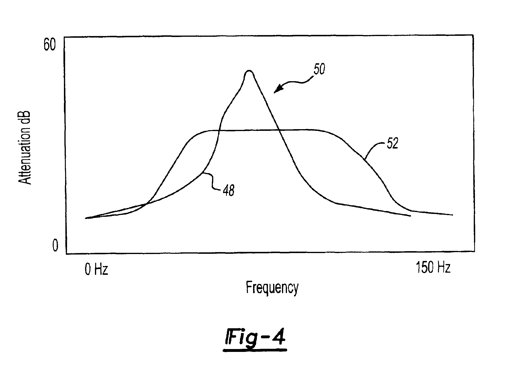
The engine generates low frequency noise that has a noise profile with a peak noise.
In a preferred embodiment, the resonator attenuates the peak noise resulting in an attenuated engine noise level.

Method used


Image

  • Resonator for active noise attenuation system
  • Resonator for active noise attenuation system
  • Resonator for active noise attenuation system

Examples


Embodiment Construction

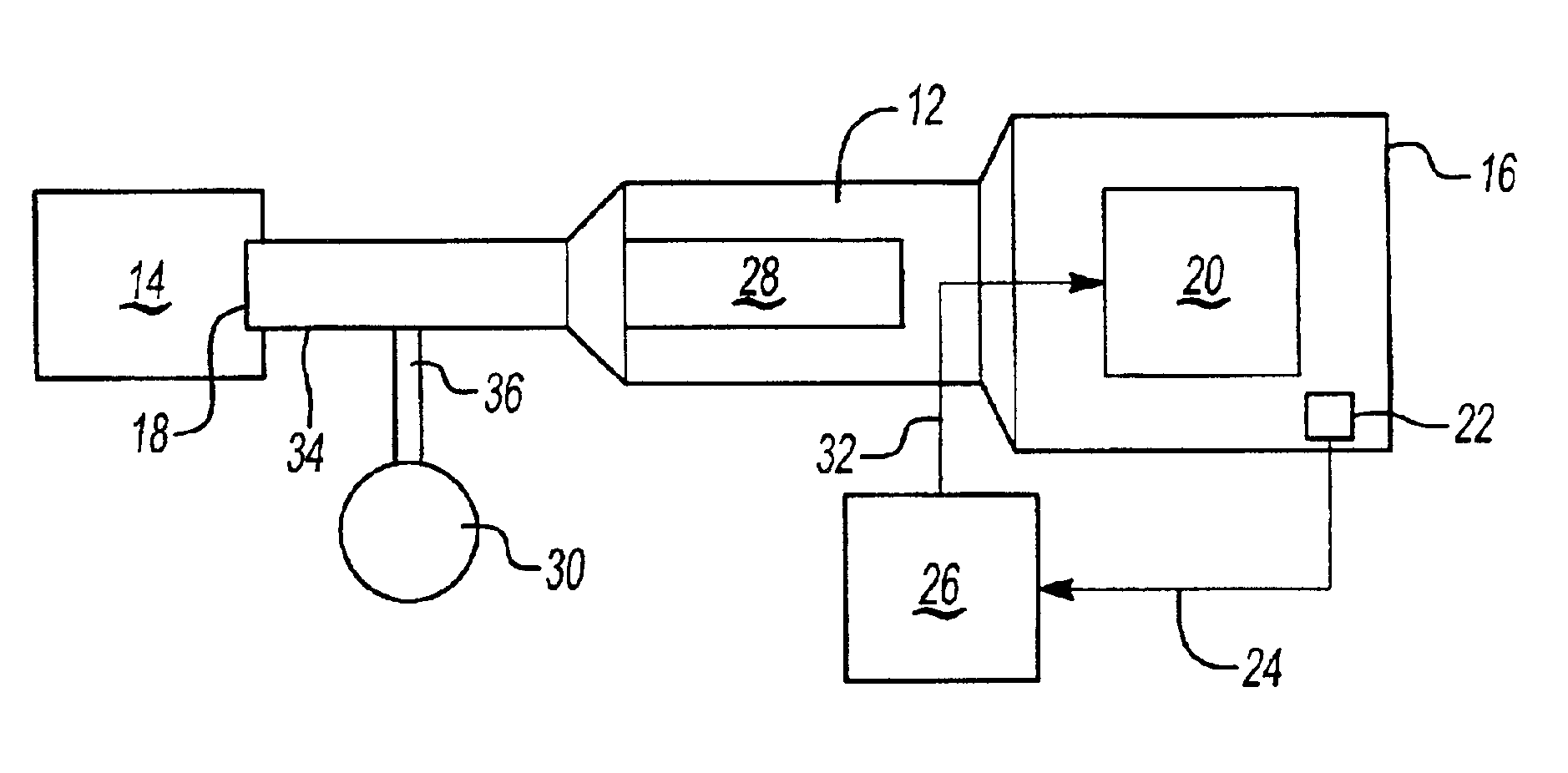
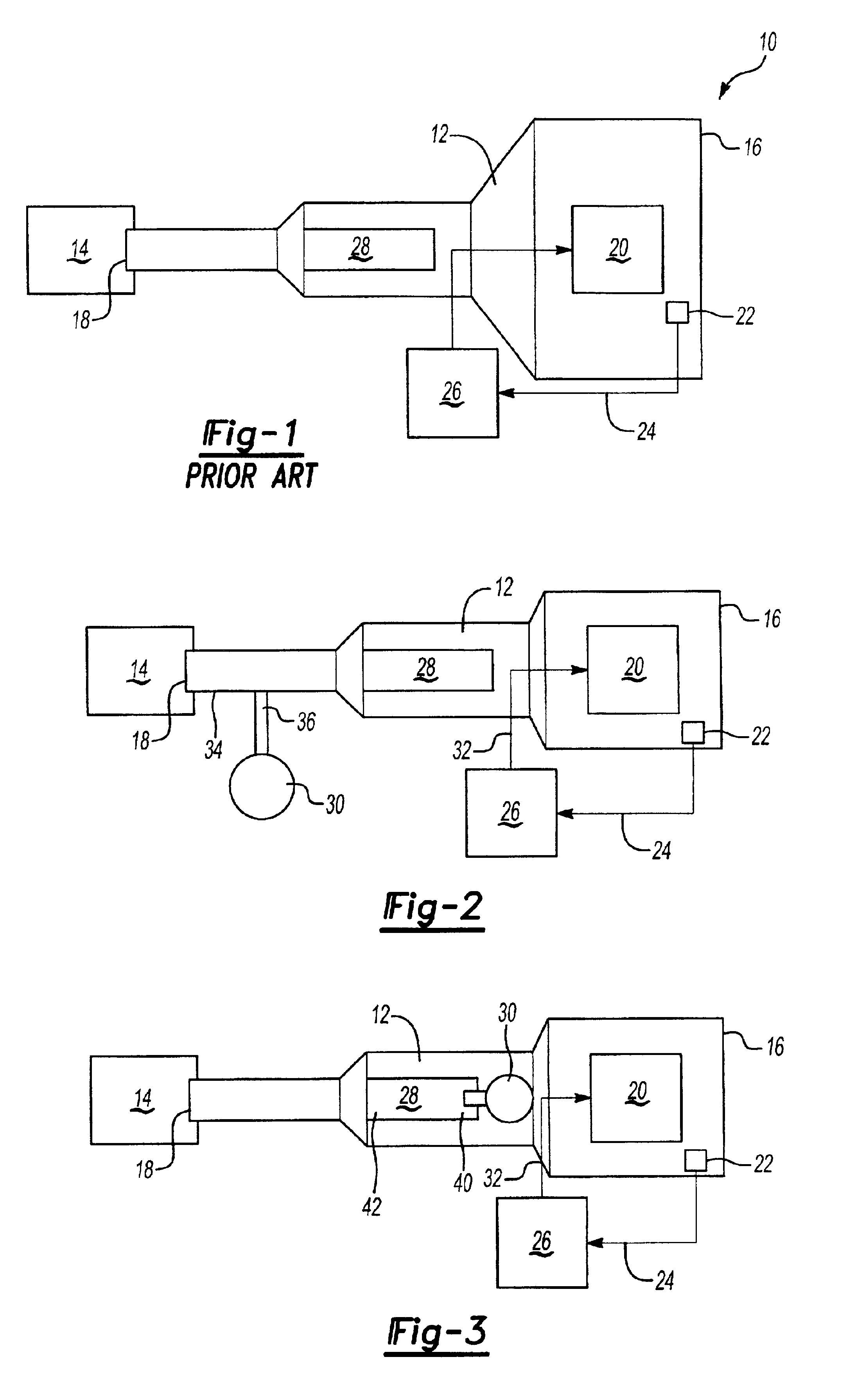
[0017]Referring to the drawings, FIG. 1 shows a known noise attenuation system 10 including an air inlet duct housing 12 forming part of an air induction system for an internal combustion engine 14. The air inlet duct housing 12 has an inlet end 16 and an outlet end 18 that is operably connected to the engine 14. Typically the inlet end 16 is of greater diameter than the outlet end 18.

[0018]A speaker assembly 20 is mounted within the air inlet duct housing 12 to face the inlet 16. A sound detector 22, such as a microphone, is mounted in front of the speaker 20 to detect engine noise. The microphone 22 generates a noise signal 24 that corresponds to the detected noise. The signal 24 is sent to a controller, microprocessor, or other similar device 26 where the signal is phase-shifted. Preferably, the signal 24 is phase-shifted 180 degrees and is then sent to the speaker 20. The speaker 20 generates a sound field based on the phase-shifted signal to cancel out the detected engine noise...


PUM


Abstract

An active noise attenuation system for an air induction assembly is operably connected to an engine that generates a low frequency noise having a noise profile defining a peak noise. The system has an air inlet duct housing with an inlet and an outlet connected to the engine. A resonator is supported by the housing and is positioned between a speaker assembly and the engine to attenuate the peak noise resulting in an attenuated low frequency engine noise. A microphone senses the attenuated low frequency engine noise and generates an attenuated low frequency engine noise signal. A controller receives and phase shifts the signal and sends the signal to the speaker to generate a sound field to cancel or reduce the attenuated low frequency engine noise signal.

Description

RELATED APPLICATION[0001]This application claims priority to provisional application No. 60 / 205,731 filed on May 19, 2000.BACKGROUND OF THE INVENTION[0002]1. Field of the Invention[0003]This invention relates to a resonator that works in conjunction with an active noise cancellation module to reduce low frequency engine noises.[0004]2. Related Art[0005]Internal combustion engines include air induction systems for conducting air to engine cylinders. Engine noise is propagated through the air induction systems, which is undesirable. Noise attenuation mechanisms have been installed within the air induction systems to reduce these noises. For this application, this noise attenuation mechanism is referred to as an Active Noise Cancellation (ANC) system and includes a speaker, a microphone, and a signal generator that are mounted within an air inlet duct housing. The microphone detects the noise and generates a noise signal that is sent to the signal generator. The signal generator phase-...

Claims


Application Information

Patent Timeline
Patent Type & Authority Patents(United States)
IPC IPC(8): G10K11/178G10K11/00G10K11/172
CPCG10K11/172G10K11/1788F02M35/125F02M35/1261G10K11/17855G10K11/17857G10K11/17861G10K11/17873G10K11/17875
Inventor STUART, PHILIP EDWARD ARTHUR
Owner 3840620 CANADA
Learn More