Electric machine

a technology of electric motors and electric motors, applied in the field of electric machines, can solve the problems of limited torque the motor can deliver, limited maximum electric field that can be applied to the motor, and particular trouble in the direction of linear motors, etc., and achieves the effects of high power-to-weight ratio, high output, and fast pa

Inactive Publication Date: 2005-09-06
VOLVO LASTVAGNAR AB
View PDF11 Cites 5 Cited by
  • Summary
  • Abstract
  • Description
  • Claims
  • Application Information

AI Technical Summary

Benefits of technology

[0011]In one embodiment of an electric machine configured according to the teachings of the present invention, an electric machine is provided with a very high power-to-weight ratio. This is obtained by incorporating a first and a second set of magnetic field altering components which in this preferred embodiment is made of iron powder or ferrite. The electric machine can be used as a generator or a motor. As a generator, it can deliver a high output compared to its size. When used as a motor, it can accelerate at a fast pace due to the low mass of the moving parts.
[0012]In an advantageous first development (version) of the electric machine, the second set of magnetic field altering components is made of permanent magnets. This further improves the efficiency of the electric machine.
[0013]In an advantageous second development of the electric machine, the first set of magnetic field altering components are made of air coils. This improves the acceleration ability of the electric machine.
[0014]In an advantageous third development of the electric machine, the electric machine comprises a plurality of first members. This gives a polyphase electric machine. The advantage of this is that it improves the controllability of the electric machine when used as a motor and the continuous power output when used as a generator.

Problems solved by technology

A problem with electric motors is that the torque the motor can deliver is limited by the ferro-magnetic core which will saturate at a certain current level.
The problem is particular troublesome when it comes to linear motors.
The moving part of the motor, in this application referred to as the rotor, is often limited in size and thus the maximum electric field that can be applied to it is limited.
This leads to an insufficient acceleration in different applications.
In applications where a linear motor is used to control an electrically actuated valve, the limited torque is apparent.
These systems are difficult to control and it is only possible to adjust the valves slightly during a cycle.
This is difficult to achieve with conventional electric machines since such machines have a relation between the electric force and the mass of the rotor which is about ten times too low.

Method used


Image

  • Electric machine
  • Electric machine
  • Electric machine

Examples


Embodiment Construction

[0027]The preferred embodiments of the invention and developments described below must be regarded solely as examples and in no way limit the scope of the patent claims. In the preferred embodiments described herein, the same reference numbers in the various figures relate to the same type of parts. Each part is therefore not described in detail in all preferred embodiments.

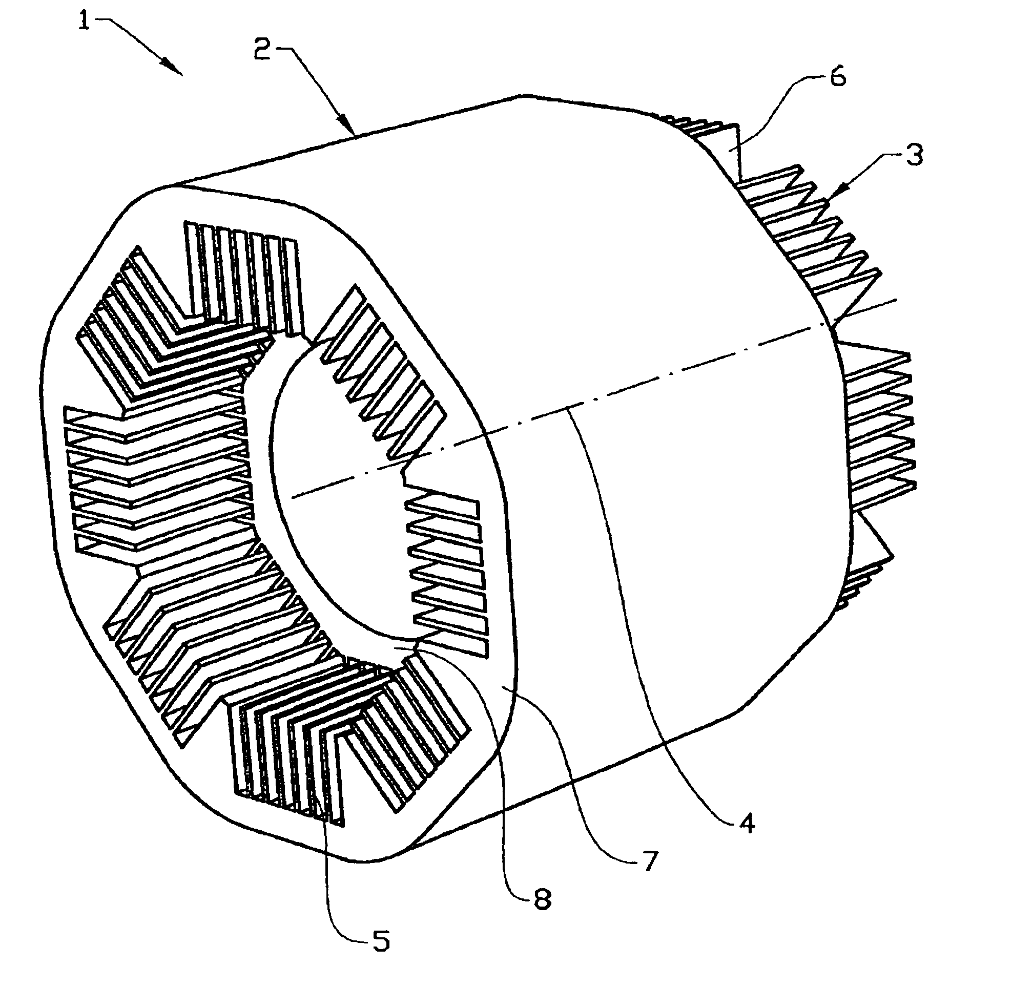
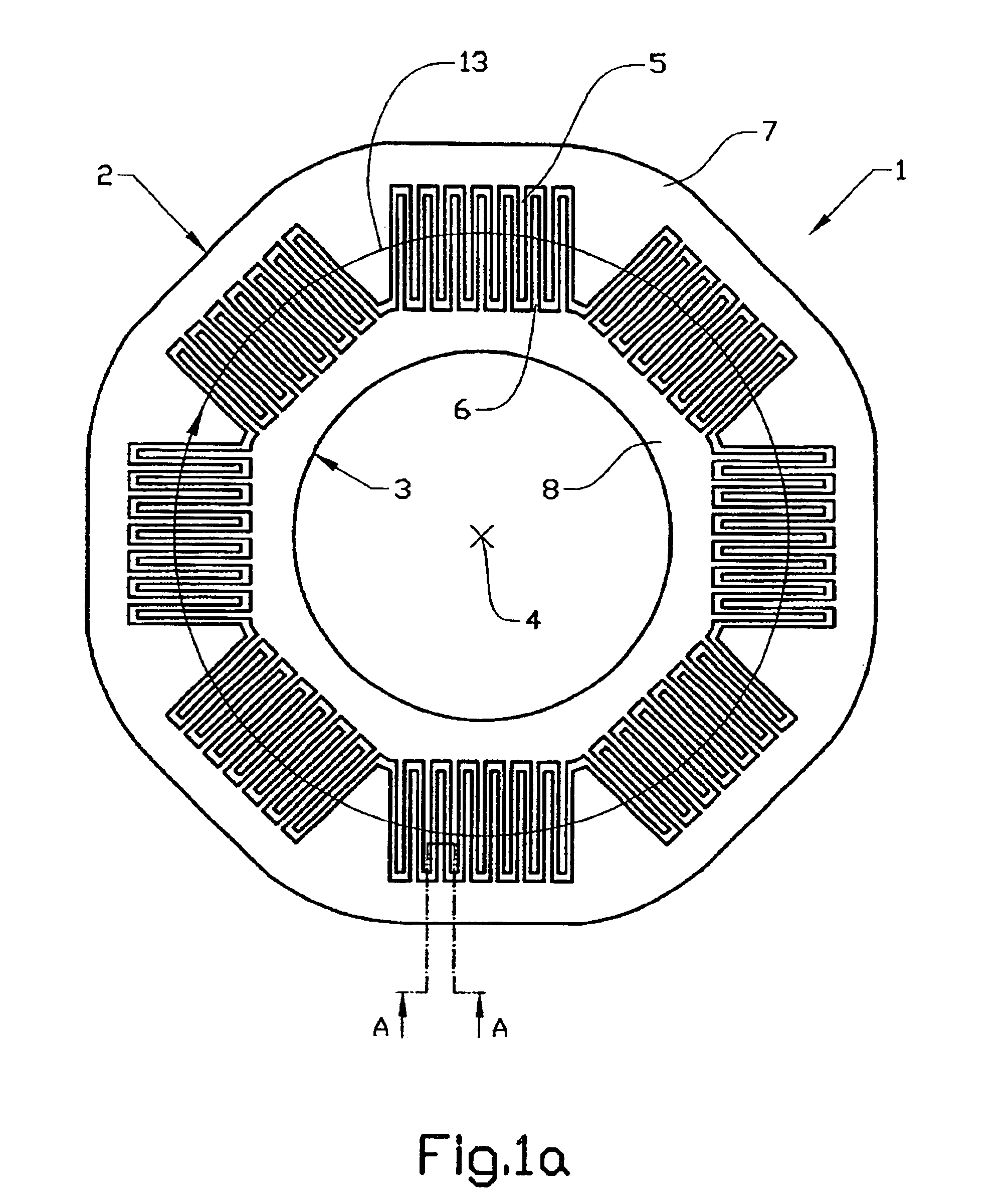
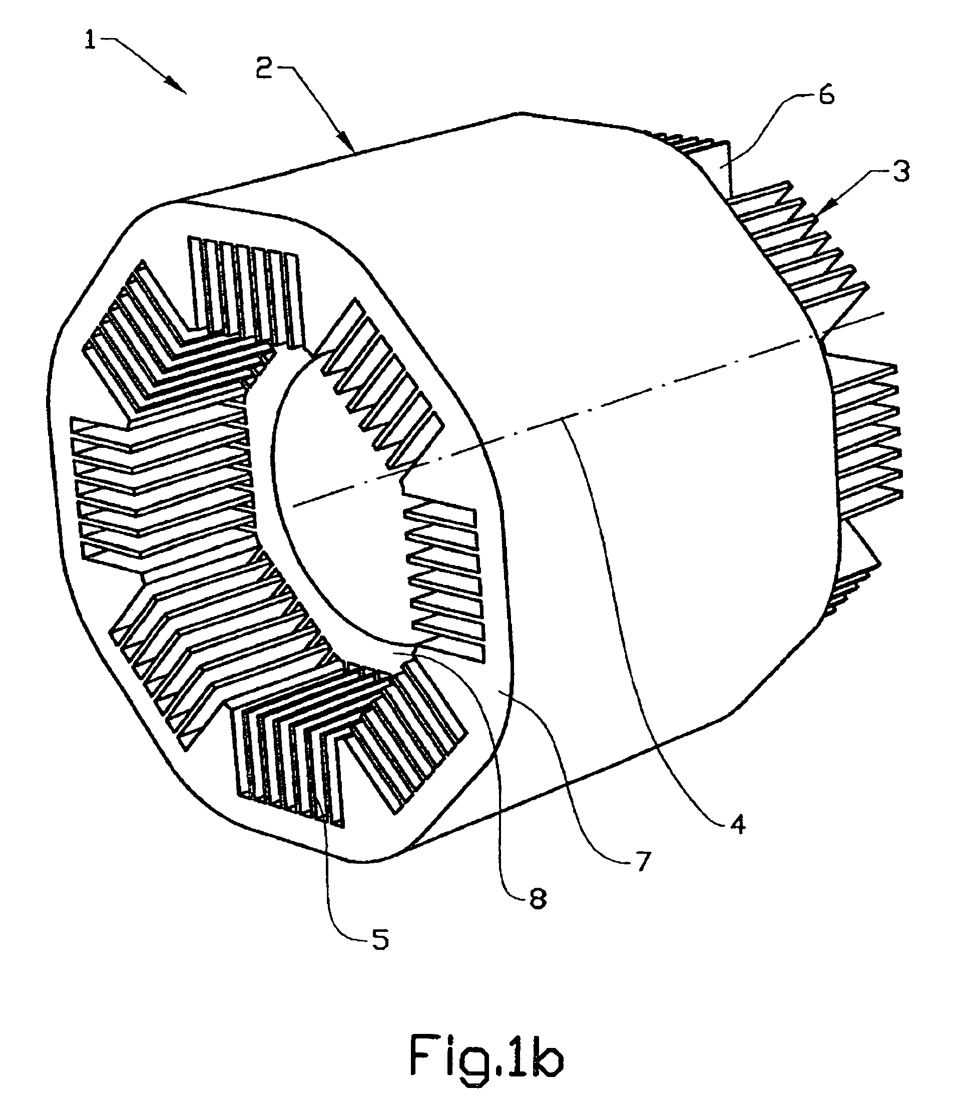
[0028]In a first preferred embodiment of an electric machine 1 that is configured according to the teachings of the invention, the electric machine is arranged in a circular configuration as depicted in FIGS. 1a, 1b, 2a and 2b. The electric machine comprises a first member 2, which will be referred to as the stator 2, and a second member 3, which will be referred to as the rotor 3. The stator 2 is normally fixed by mounting it to a rigid structure, but it is also possible to mount it in a movable manner. The rotor 3 is movable in relation to the stator 2 about the longitudinal axis 4 of the machine. In FIG. 1a, t...


PUM


Abstract

An electric machine including a first member and a second member. The second member is movable in relation to the first member. The first member has at least one coil and the first and the second members both include a plurality of segments, where each segment of the first member comprises a plurality of sections have a first magnetic conducting material. Each segment of the second member includes a plurality of sections having a second magnetic conducting material, and in which the first and the second member includes a closed magnetic circuit.

Description

CROSS-REFERENCE TO RELATED APPLICATION[0001]The present application is a continuation patent application of International Application No. PCT / SE02 / 02410 filed 19 Dec. 2002, now abandoned, which was published in English pursuant to Article 21(2) of the Patent Cooperation Treaty, and which claims priority to both Swedish Application No. 0104378-5 filed 21 Dec. 2001. Said applications are expressly incorporated herein by reference in their entireties.TECHNICAL FIELD[0002]The present invention relates to an electric machine comprising a stator and a rotor, where the rotor is movable in respect to the stator about the longitudinal axis of the electric machine.BACKGROUND ART[0003]Electric machines are well known in the art. They can be either of the electric motor type that produces a force when electric energy is supplied, or of the generator type that generates electric energy when a mechanical force is applied to the generator. There exists both rotary and linear electric machines. A p...

Claims


Application Information

Patent Timeline
Patent Type & Authority Patents(United States)
IPC IPC(8): H02K41/03H02K35/02
CPCH02K41/03
Inventor JOBSON, EDWARDMAX, ERLAND
Owner VOLVO LASTVAGNAR AB
Why Eureka
Try Eureka